Vehicle and anti-collision beam thereof

An anti-collision beam and vehicle technology, which is applied to vehicle components, power units, electric power units, etc., can solve the problems of a lot of increase in cost, difficulty in bending and forming, and high price, so as to improve the anti-collision performance and safety. Improved, low-cost effects

Active Publication Date: 2020-07-14
ZHENGZHOU YUTONG BUS CO LTD
View PDF6 Cites 0 Cited by
  • Summary
  • Abstract
  • Description
  • Claims
  • Application Information

AI Technical Summary

Problems solved by technology

[0005] The above-mentioned rear bumper is designed with a Japanese-shaped structure, although it can not only ensure the structural strength of the anti-collision beam to a certain extent, but also ensure the lightweight of the vehicle, but as the market requires higher and higher safety levels for vehicles, the The strength requirements of anti-collision beams are getting higher and higher, and to further improve the structural strength of anti-collision beams, vehicle designers currently mainly use higher-strength materials to make anti-collision beams with Japanese-shaped cross-sections. The higher the strength, the more expensive the price, which will increase the cost of the vehicle a lot, and the higher the strength of the material, the more difficult it is to bend and form; in addition, the anti-collision beam can be improved by increasing the strength of the material The capacity is limited, and it is difficult to meet the needs of vehicles that require higher protection performance, such as electric vehicles that require high protection performance of the battery compartment

Method used


Image

  • Vehicle and anti-collision beam thereof
  • Vehicle and anti-collision beam thereof
  • Vehicle and anti-collision beam thereof

Examples


Embodiment Construction

[0047] The specific embodiments of the present invention will be further described below in conjunction with the accompanying drawings.

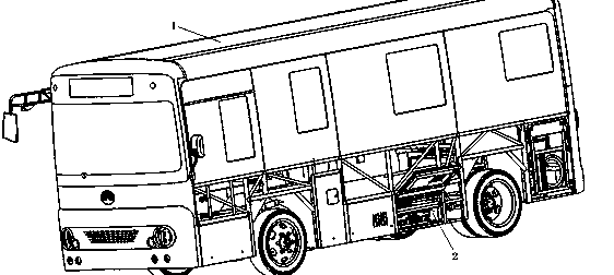
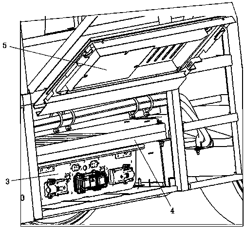
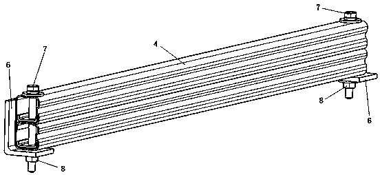
[0048] Embodiment 1 of the vehicle of the present invention, such as figure 1 and figure 2 As shown, the vehicle in the present embodiment 1 is an electric vehicle, and the electric vehicle includes a vehicle frame 1, a battery compartment 2 is arranged on the inside of the vehicle frame 1, and a battery 3 is installed in the battery compartment 2, in order to prevent the electric vehicle from being hit by other vehicles When destroying the battery 3 and causing the battery 3 to leak and burn, a battery anti-collision beam 4 is horizontally installed at the hatch of the battery compartment 2; a hatch 5 is also hingedly installed at the hatch of the battery compartment 2, and the hatch 5 can pass through The hinged structure is lifted upwards. Of course, in other embodiments, the vehicle can also be other types of vehicles, such as fuel ve...


PUM


Abstract

The invention relates to the technical field of vehicle parts, in particular to a vehicle and an anti-collision beam thereof. The anti-collision beam in the vehicle is provided with an outer force bearing wall used for bearing impact and an inner force bearing wall which is arranged at an interval with the outer force bearing wall and used for being supported on a vehicle frame. A supporting wallis arranged between the outer force bearing wall and the inner force bearing wall, the supporting wall and the corresponding parts of the outer force bearing wall and the inner force bearing wall jointly define a closed cavity, an additional supporting wall made of composite materials is further arranged between the outer force bearing wall and the inner force bearing wall, and the additional supporting wall is supported between the outer force bearing wall and the inner force bearing wall. The anti-collision beam can be used for solving the problem that in the prior art, the anti-collision capacity of an anti-collision beam is limited, and then the safety performance and the deformation resistance of a vehicle can be improved.

Description

technical field [0001] The invention relates to the technical field of auto parts, in particular to a vehicle and an anti-collision beam thereof. Background technique [0002] Vehicle safety is an important issue that needs to be considered in vehicle design, and the anti-collision beam is an important structure to ensure the safety of vehicles. [0003] Traditional anti-collision beams mainly consider their mechanical properties when designing, as long as their structural strength is sufficient, while ignoring the weight of the anti-collision beam itself. As the automotive industry has higher and higher requirements for energy saving and emission reduction, the requirements for lightweight vehicles are also getting higher and higher. The traditional design idea of ​​only considering the mechanical properties and ignoring the weight of the anti-collision beam has been gradually eliminated, and the design of high structural strength And light-weight anti-collision beams have...

Claims


Application Information

Patent Timeline
IPC IPC(8): B60K1/04
CPCB60K1/04
Inventor 刘刚李建平崔崇桢孙明英张贺
Owner ZHENGZHOU YUTONG BUS CO LTD
Why Eureka
Try Eureka