Positioning tension device for mounting steel structural member

A technology of tensioning device and steel structure, which is applied in the field of positioning and tensioning device for the installation of steel structure components, and can solve problems such as inability to guarantee welding quality, investment in multiple measures, and increasing the lifting weight of components

Pending Publication Date: 2020-07-14
CHINA 22MCC GROUP CORP
View PDF0 Cites 0 Cited by
  • Summary
  • Abstract
  • Description
  • Claims
  • Application Information

AI Technical Summary

Problems solved by technology

[0002] At present, there are more and more steel structure public buildings, and there are more and more long-span components. During the installation process, because of the large deformation of the long-span components, it cannot be positioned accurately and cannot be tightened. The phenomenon, the result is that the gap in the welding position of the component is too large, and the welding quality cannot be guaranteed
If in order to ensure that the large-span components will not be deformed during the hoisting process, a lot of

Method used


Image

  • Positioning tension device for mounting steel structural member
  • Positioning tension device for mounting steel structural member
  • Positioning tension device for mounting steel structural member

Examples


example 1

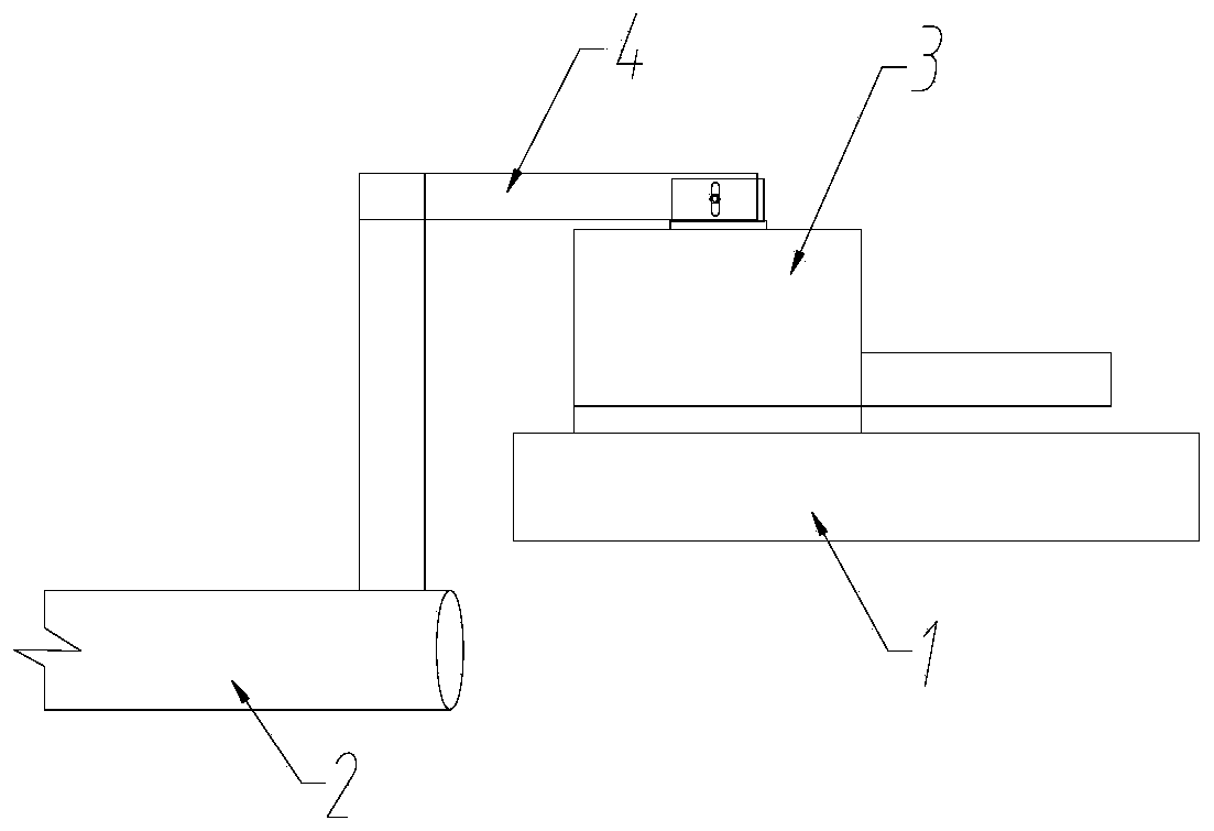
[0033] Example 1: Reference image 3 and Figure 4 , the welding base 7 is concave, and the welding base 7 is buckled upside down on the fixed steel structure (that is, the fixed steel structure 1), and the two sides of the concave shape are fixedly connected with the fixed steel structure 1, and the fixed connection at this position can be welding.

example 2

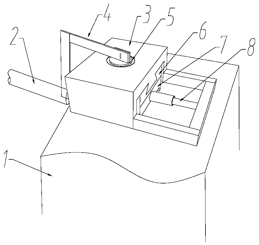
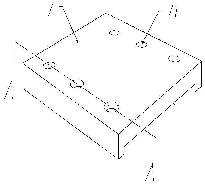
[0034] Example 2: Reference Figure 5 and Image 6 As shown, the connection between the dismountable base 6 and the welded base 7 is connected by bolts. Specifically, six threaded holes 71 are arranged on the upper part of the welded base 7, and six countersunk holes are arranged on the positions corresponding to the six threaded holes on the disassembled base 6. 61, just disassemble base 6 and welding base 7 bolts are hinged by countersunk head bolts.

example 3

[0035] Example 3: The groove 62 on the top of the disassembly base 6 is a through chute with a dovetail-shaped cross section, and the slide rail 32 at the bottom of the sliding block 3 and a long protruding slide rail with a dovetail-shaped cross-section. In this example, the sliding block 3 slides in translation on the dismountable base 6 .


PUM


Abstract

The invention relates to a positioning tension device for mounting a steel structural member. The positioning tension device comprises a welding base, a convenient-to-detach base, a sliding block, a rotating block, an L shaped clamping head and a jack; the welding base is fixedly connected with a fixed steel structure; the convenient-to-detach base is fixedly connected above the welding base; a groove is formed in the top of the convenient-to-detach base; a sliding rail is arranged at the bottom of the sliding block; the sliding block is movably mounted on the convenient-to-detach base; a circular groove is formed in the upper part of the sliding block; a spherical bearing is arranged in the circular groove; the rotating block is mounted above the spherical bearing and comprises ear platesmounted at the lower part and upper part of the interior of the circular groove; reamed holes are formed in the ear plates; the ear plates are hinged to the upper end of the L shaped clamping head; amounting component is connected with the lower end of the L shaped clamping head; the sliding block is provided with the jack; the fixed end of the jack is fixed with a foundation; the movable end ofthe jack is connected with the sliding block; and the power direction of the jack is parallel with the sliding rail and the groove. The positioning tension device is small in size, light in weight and high in turnover efficiency, can be manually carried, and saves plenty of cost for investing measures and hoisting equipment.

Description

technical field [0001] The invention relates to the installation and construction technology of large-span steel components, in particular to a positioning and tensioning device for installing steel structural components. Background technique [0002] At present, there are more and more steel structure public buildings, and there are more and more long-span components. During the installation process, because of the large deformation of the long-span components, it cannot be positioned accurately and cannot be tightened. The phenomenon, the result is that the gap in the welding position of the component is too large, and the welding quality cannot be guaranteed. If in order to ensure that the long-span components do not deform during the hoisting process, a lot of measures are required to invest, which increases the lifting capacity of the components, and then increases the type of hoisting equipment, and the cost increases geometrically. The problem of installation, positi...

Claims


Application Information

Patent Timeline
IPC IPC(8): E04G21/18E04B1/342
CPCE04B1/342E04G21/1841
Inventor 于海龙毕强
Owner CHINA 22MCC GROUP CORP
Why Eureka
Try Eureka