Shift register, gate drive circuit and display control method

A technology of shift register and control terminal, which is applied in the field of gate drive circuit and display control, and shift register, which can solve the problems of poor horizontal stripes and difficult maintenance of potential in LHB, and reduce the problems of poor horizontal stripes, easy potential and gate voltage signal. stable effect

Active Publication Date: 2022-06-21
BOE TECH GRP CO LTD +1
View PDF0 Cites 0 Cited by
  • Summary
  • Abstract
  • Description
  • Claims
  • Application Information

AI Technical Summary

Problems solved by technology

[0003] In view of the shortcomings of the existing methods, the present application proposes a shift register, a gate drive circuit and a display control method to solve the problem in the prior art that the potential of the pull-up node PU is not easy to maintain and the LHB horizontal stripes are prone to occur. technical problem

Method used


Image

  • Shift register, gate drive circuit and display control method
  • Shift register, gate drive circuit and display control method
  • Shift register, gate drive circuit and display control method

Examples


Embodiment Construction

[0033] The application is described in detail below, and examples of embodiments of the application are illustrated in the accompanying drawings, wherein the same or similar reference numerals refer to the same or similar components or components having the same or similar functions throughout. Also, detailed descriptions of known technologies are omitted if they are not necessary for illustrating features of the present application. The embodiments described below with reference to the accompanying drawings are exemplary and are only used to explain the present application, but not to be construed as a limitation on the present application.

[0034] It will be understood by those skilled in the art that, unless otherwise defined, all terms (including technical and scientific terms) used herein have the same meaning as commonly understood by one of ordinary skill in the art to which this application belongs. It should also be understood that terms, such as those defined in a g...


PUM


Abstract

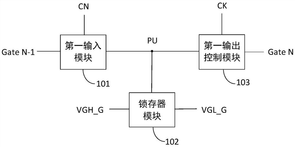
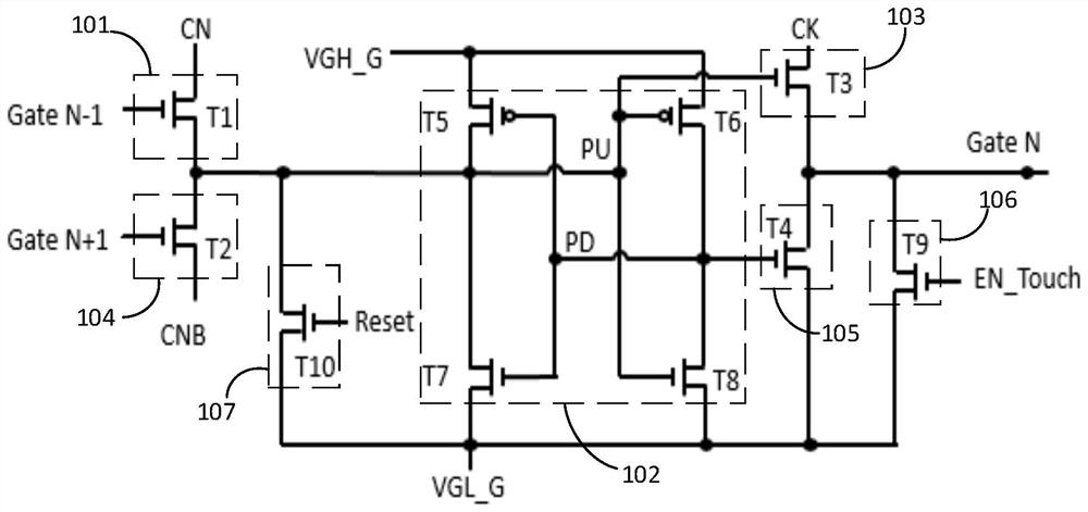
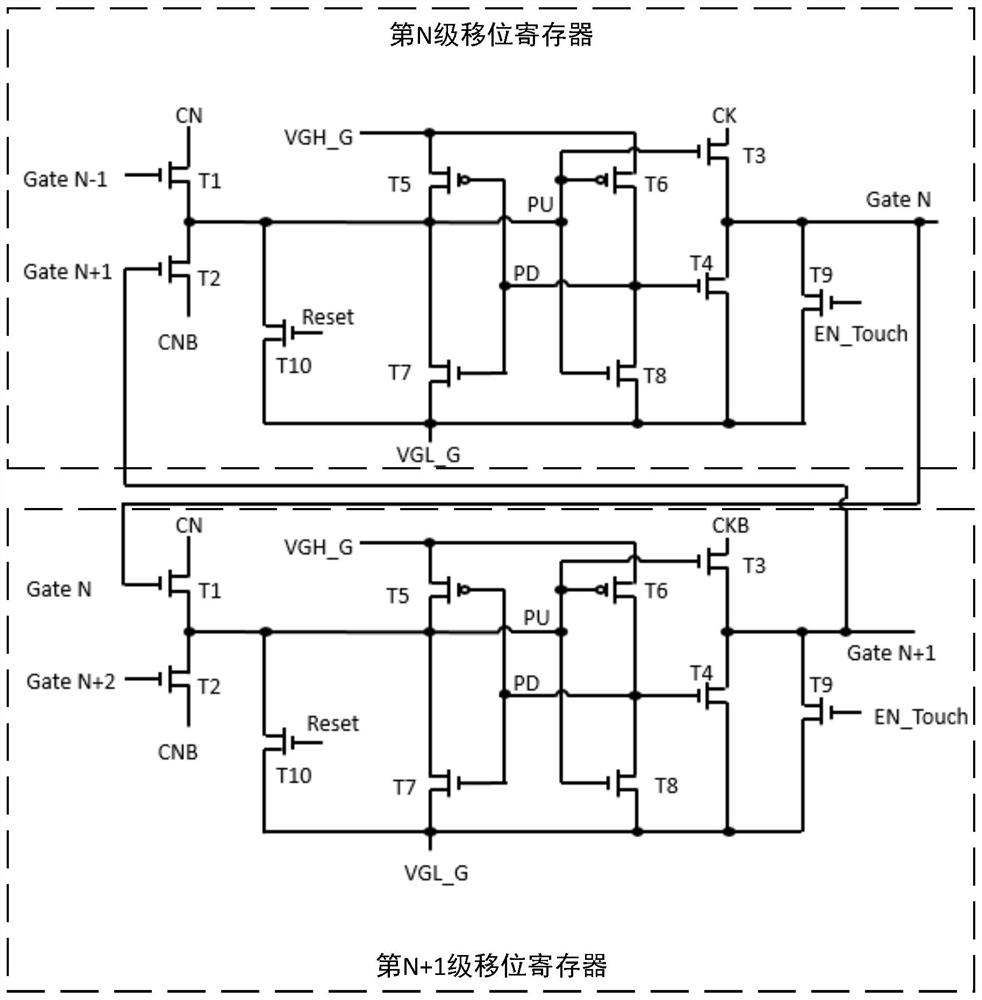
The application provides a shift register, a gate drive circuit and a display control method. The shift register includes: a first input module, a latch module, and a first output control module; the control terminal, the first terminal, and the second terminal of the first input module are respectively connected to the first gate voltage signal terminal and the first latch The signal end and the pull-up node are electrically connected; the first control end, the second control end, the first end, and the second end of the latch module are respectively connected to the pull-up node, the pull-down node, the first adjustment signal end, and the second adjustment The signal terminal is electrically connected; the control terminal, the first terminal, and the second terminal of the first output control module are respectively electrically connected to the pull-up node, the clock signal terminal, and the output terminal; the technical solution of the application is easier to realize the pull-up node in the display stage The potential is stable, so as to ensure the stability of the grid voltage signal output by the first output control module, and reduce the phenomenon of poor LHB stripes and poor split screens.

Description

technical field [0001] The present application relates to the technical field of liquid crystal display, and in particular, the present application relates to a shift register, a gate driving circuit and a display control method. Background technique [0002] At present, the GOA (Gate Driver On Array, array substrate gate driver) driver circuit in TDDI (Touch and Display Driver Integration) products mainly adopts the 10T2C circuit model, that is, 10 TFT (Thin Film Transistor-Liquid, thin film transistor) and the circuit model formed by 2 capacitors. In this circuit model, the potential of the pull-up node is mainly maintained by the capacitor. When the leakage of some TFTs is large, the potential of the pull-up node is not easy to maintain in the display stage, the output signal is unstable, and LHB (Long Horizon Blanking, long Horizontal blank area) bad horizontal stripes, when the leakage is more serious, there will also be a phenomenon of poor split screen, which serious...

Claims


Application Information

Patent Timeline
Patent Type & Authority Patents(China)
IPC IPC(8): G11C19/28G09G3/20
CPCG11C19/28G09G3/20G09G2310/0286
Inventor 罗鹏霍培荣王志强程海明张建平
Owner BOE TECH GRP CO LTD
Why Eureka
Try Eureka