
Synchronous broadcast information sending method and device and synchronous broadcast information detection method and device

A technology for synchronous broadcasting and information transmission, which is applied in the field of communication and can solve problems such as complexity

Active Publication Date: 2020-07-14
DATANG MOBILE COMM EQUIP CO LTD
View PDF13 Cites 2 Cited by
  • Summary
  • Abstract
  • Description
  • Claims
  • Application Information

AI Technical Summary

Problems solved by technology

[0003] In the sidelink communication of the V2X system, the Orthogonal Frequency Division Multiplexing (Cyclic Prefix-Orthogonal Frequency Division Multiplexing, CP-OFDM) waveform of the cyclic prefix may be used, and the positive Discrete Fourier Transform-spread-Orthogonal Frequency Division Multiplexing (DFT-s-OFDM) waveform, due to the limitation of data multiplexing under DFT-s-OFDM waveform, it is necessary to design different waveforms for different Direct link-Sidelink Synchronization Signal and Physical Broadcast Channel Block (S-SSB), which will bring the complexity of S-SSB design and the complexity of standard formulation, and will affect the implementation of subsequent products brings complexity

Method used


Image

  • Synchronous broadcast information sending method and device and synchronous broadcast information detection method and device
  • Synchronous broadcast information sending method and device and synchronous broadcast information detection method and device
  • Synchronous broadcast information sending method and device and synchronous broadcast information detection method and device

Examples


Embodiment 1

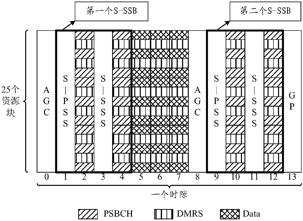
[0081] Embodiment 1: see Figure 5 , is a schematic diagram of the distribution of the next time slot of the CP-OFDM waveform; as shown in the figure, for the first S-SSB, S-PSS occupies symbol #1, S-SSS occupies symbol #3, PSBCH signal occupies symbol #2 and #4; For the second S-SSB, the S-PSS occupies symbol #9, the S-SSS occupies symbol #11, and the PSBCH signal occupies symbols #10 and #12.

[0082] Symbols #5 to #7 are data transmission areas. If the data transmission area and the S-SSB located in front of the data transmission area belong to the same user receiving, then the symbol #5 does not need to be used for AGC training, such as Figure 5 As shown; if the data transmission area and the S-SSB located in front of the data transmission area belong to different terminals to receive, symbol #5 needs to be AGC trained, and symbol #5 may be deleted to perform rate re-matching. The distribution diagram of the gap is shown in the Figure 6 shown.

[0083] The above S-SSB...

Embodiment 2

[0085] Example 2: see Figure 8 , is a schematic diagram of the distribution of the next time slot of the DFT-s-OFDM waveform; as shown in the figure, for the first S-SSB, S-PSS occupies symbol #1, S-SSS occupies symbol #3, and PSBCH signal occupies symbol # 2 and #4; for the second S-SSB, S-PSS occupies symbol #9, S-SSS occupies symbol #11, PSBCH signal occupies symbols #10 and #12.

[0086] Symbols #5 to #7 are data transmission areas. If the data transmission area and the S-SSB located in front of the data transmission area belong to the same user receiving, then the symbol #5 does not need to be used for AGC training, such as Figure 8 As shown; if the data transmission area and the S-SSB located in front of the data transmission area belong to different terminals to receive, symbol #5 needs to be AGC trained, and symbol #5 may be deleted to perform rate re-matching. The distribution diagram of the gap is shown in the Figure 9 shown.

[0087] The above S-SSB may also i...

Embodiment 3

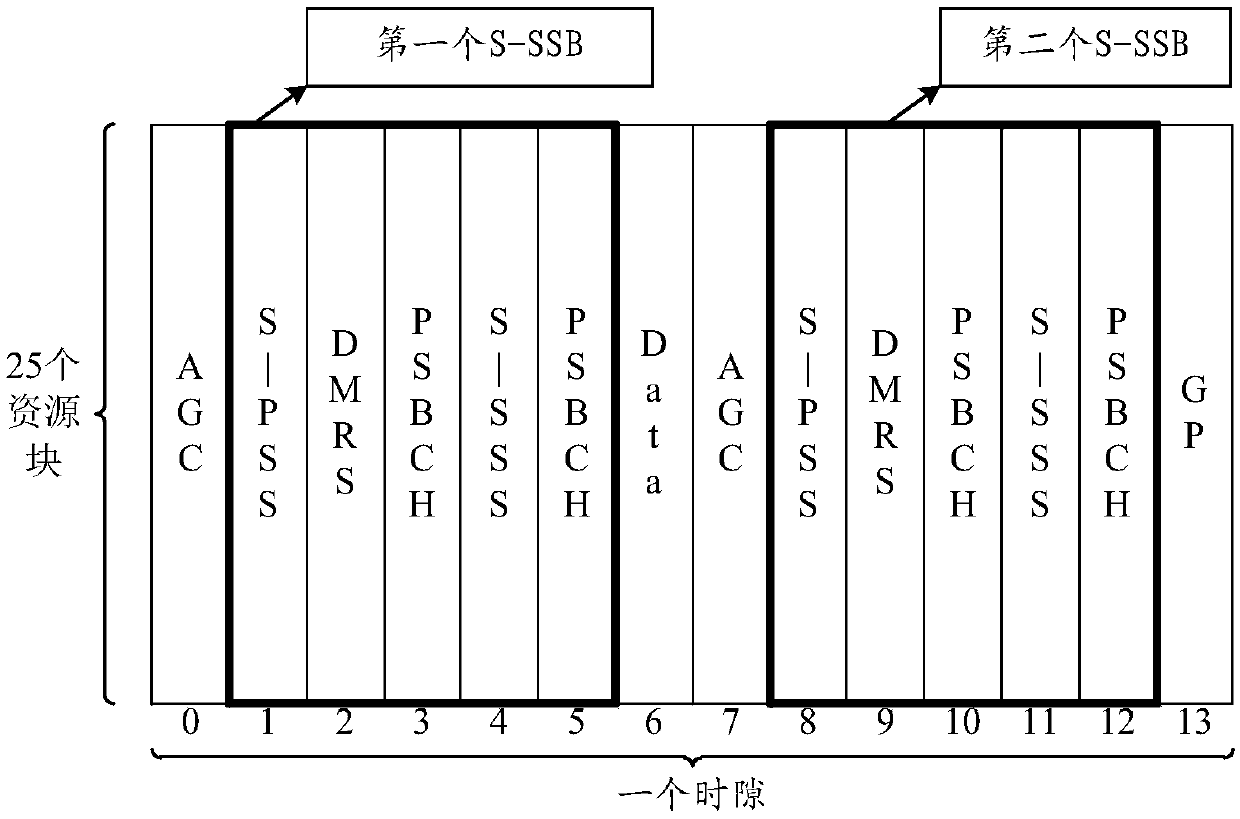
[0088] Embodiment 3: see Figure 10 , is a schematic diagram of the distribution of the next time slot of the CP-OFDM waveform; #3; For the second S-SSB, the S-PSS occupies symbol #12, the S-SSS occupies symbol #10, and the PSBCH signal occupies symbols #9 and #11.

[0089] Symbols #5 to #7 are data transmission areas. If the data transmission area and the S-SSB located in front of the data transmission area belong to the same user receiving, then the symbol #5 does not need to be used for AGC training, such as Figure 10 As shown; if the data transmission area and the S-SSB located in front of the data transmission area belong to different terminals to receive, symbol #5 needs to perform AGC training, and symbol #5 may be knocked out, so as to perform rate re-matching. Schematic diagram of the distribution of data transmission areas in Figure 6 Consistent, no more details here.

[0090] In this embodiment, the symbols occupied by the PSBCH signal in the S-SSB under the CP...


PUM


Abstract

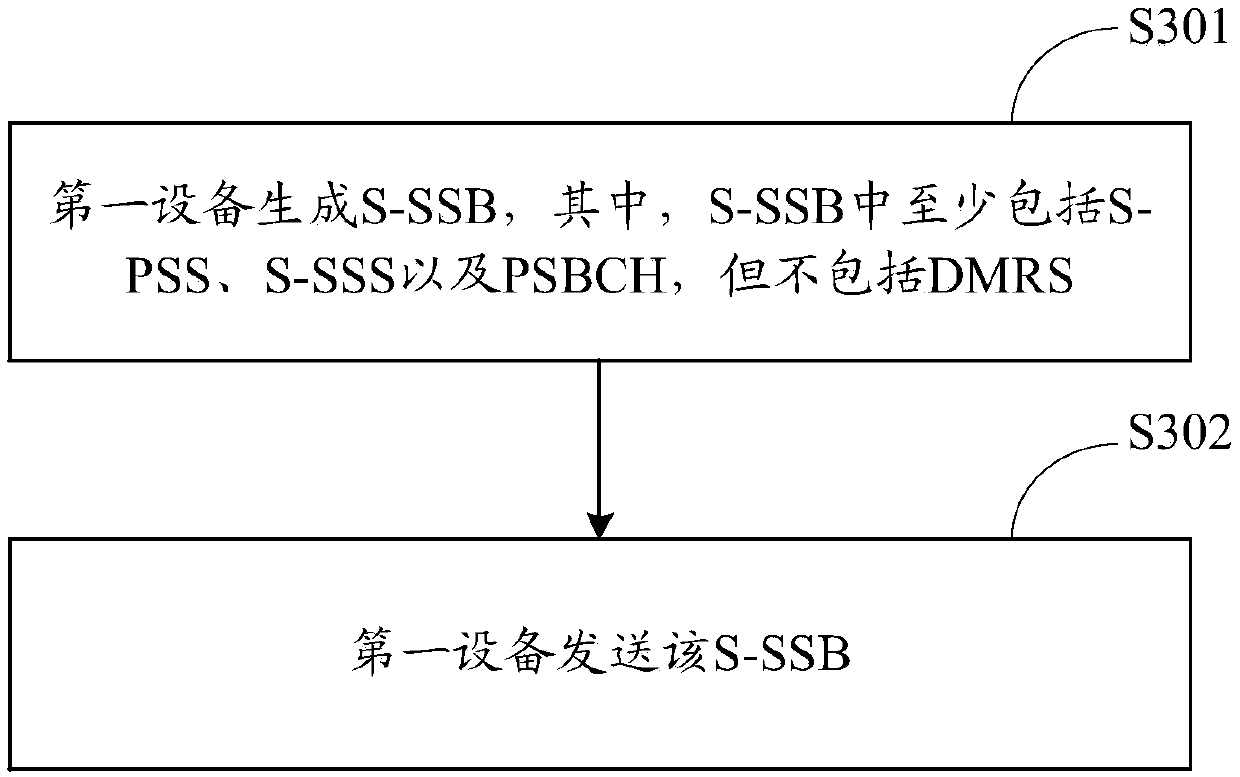
The invention discloses a synchronous broadcast information sending method and device and a synchronous broadcast information detection method and device. The method comprises the steps that first equipment generates a straight-through link-synchronous signal and a physical broadcast channel block S-SSB, wherein the S-SSB at least comprises a straight-through link-primary synchronization signal S-PSS, a straight-through link-secondary synchronization signal S-SSS and a physical straight-through link broadcast channel PSBCH signal, and does not comprise a demodulation reference signal DMRS; thefirst device sends the S-SSB; according to the method disclosed in the invention, the same S-SSB is realized under the CP-OFDM waveform and the DFT-s-OFDM waveform.

Description

technical field [0001] The present application relates to the technical field of communication, and in particular to a method and device for sending and detecting synchronous broadcast information. Background technique [0002] In the 5G new radio access technology (NR Radio Access, NR) intelligent networked vehicle technology (Vehicle-to-Everything, V2X) system, the short-distance communication port 5 (ProximityCommunication Port 5, PC5 port) is used between terminals for direct communication. Before the business data is transmitted, it is first necessary to establish synchronization between the two communicating terminals at the PC5 port. The method of establishing synchronization is that one terminal A sends synchronization and broadcast signals, and another terminal B receives the synchronization and broadcast signals sent by terminal A. Once terminal B receives and demodulates successfully, the two terminals can establish synchronization, which is the next step. Commu...

Claims


Application Information

Patent Timeline
IPC IPC(8): H04W4/06H04W4/40H04W56/00
CPCH04W4/06H04W4/40H04W56/001H04W56/00H04L5/00
Inventor 任晓涛赵锐郑方政
Owner DATANG MOBILE COMM EQUIP CO LTD
Learn More