Laparoscopic suturing device

A suturing device and laparoscope technology, applied in the field of medical devices, can solve the problems of insufficient rotation of the suture needle, increase the difficulty of the operation, adverse effects of the force on the suture needle, etc., achieve convenient and light operation and use, improve the success rate of the operation, and ensure the accuracy of the operation. effect in place

Pending Publication Date: 2020-07-17
邦尼医疗科技(常州)有限公司
View PDF0 Cites 2 Cited by
  • Summary
  • Abstract
  • Description
  • Claims
  • Application Information

AI Technical Summary

Problems solved by technology

[0003] In the existing structure of the suture device, the rack is usually pulled by a single steel wire rope to drive the swing head to rotate, and the swing head is reset by the elastic force of the spring, so as to continuously circulate, and the structure is relatively complicated. This phenomenon makes it difficult to control the movement of the wrench during suturing, which increases the difficulty of the operation; at the same time, because a single wire rope is used to pull it, it is necessary to tighten the wrench after the suture needle is in place to adjust the position of the suture needle, and the force generated will affect the suture. Negative effect on needles, poor operational reliability

Method used


Image

  • Laparoscopic suturing device
  • Laparoscopic suturing device
  • Laparoscopic suturing device

Examples


Embodiment Construction

[0020] The present invention is described in further detail now in conjunction with accompanying drawing. These drawings are all simplified schematic diagrams, which only illustrate the basic structure of the present invention in a schematic manner, so they only show the configurations related to the present invention.

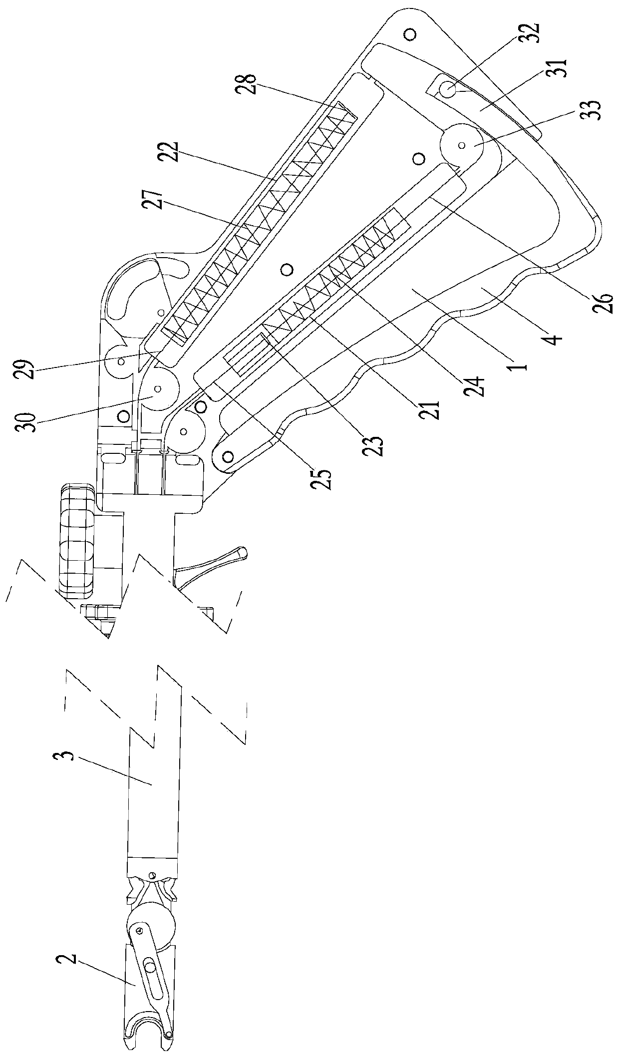
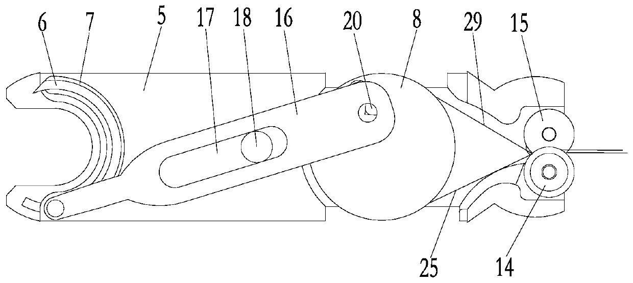
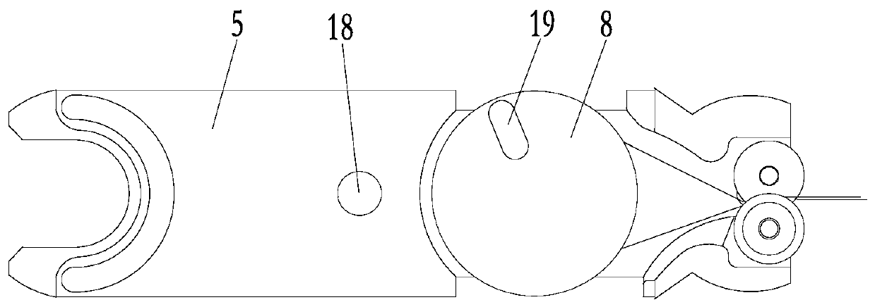
[0021] like Figure 1 to Figure 5 A laparoscopic stapler shown includes a handle 1, a swing head 2 and a holster 3 connecting the handle 1 and the swing head 2, a wrench 4 is hinged at the upper end of the handle 1, the swing head 2 has a swing head seat 5, and the swing head 2 has a swing head seat 5. The front end of the head base 5 has an arc track 7 for placing the suture needle 6, and the swing head base 5 is provided with an upper cover plate (shown in the figure) cooperating with it, and the front end of the upper cover plate cooperates with the arc track 7 to limit the suture needle 6 Location.

[0022] The rear end of the swing head seat 5 is rotate...


PUM


Abstract

The invention relates to a laparoscopic suturing device. The device comprises a handle, a swinging head and a gun sleeve, the upper end of the handle is hinged to a wrench, the swinging head is provided with a swinging head seat, the front end of the swinging head seat is provided with an arc-shaped track for placing sewing needles, the rear end of the swinging head seat is rotationally provided with a turntable, the turntable is eccentrically hinged to a swing rod for driving the sewing needles to rotate, the turntable is coaxially provided with a rotary sheave, and the handle is internally provided with a first traction steel wire of which the front end penetrates through the gun sleeve and is in winding connection with the rotary sheave along one side of the rotary sheave, and a secondtraction steel wire of which the front end penetrates through the gun sleeve and is in winding connection with the rotary sheave along the other side of the rotary sheave. According to the invention,the first traction steel wire and the second traction steel wire pull the rotary sheave to alternately rotate clockwise and anticlockwise, and the turntable drives the swing rod to drive the rotary motion of the sewing needles, so that the precise position of the rotary motion of the sewing needles is ensured, and the success rate of the operation is improved.

Description

technical field [0001] The invention relates to the technical field of medical instruments, in particular to a laparoscopic stapler. Background technique [0002] Laparoscopic surgery is a newly developed minimally invasive method, which is mainly used for intra-abdominal examination and treatment. When suturing the postoperative human tissue during the operation, the doctor fires it through the wrench on the handle of the stapler, continuously pulls and loosens the wire rope, and drives the front end to swing the head to drive the suture needle to continuously rotate, pierce the human tissue and suture. [0003] The existing structure of the stapler usually pulls the rack by a single wire rope to drive the swing head to rotate, relying on the spring back to reset the swing head, so as to continuously circulate, the structure is more complicated, and the suture needle is prone to not turning in place during the operation This phenomenon makes it difficult to control the mov...

Claims


Application Information

Patent Timeline
Patent Type & Authority Applications(China)
IPC IPC(8): A61B17/04
CPCA61B17/0469A61B17/0482A61B17/0491
Inventor 沈行周长林蒋丽华谢茹华刘建平洪卫兰
Owner 邦尼医疗科技(常州)有限公司
Why Eureka
Try Eureka