Foldable shifting chair

A technology of seat cushion and bottom frame, applied in the field of shift chairs, can solve problems such as inconvenience of use and secondary injury, and achieve the effects of convenient and labor-saving adjustment, reduced space occupation, and fewer adjustment steps.

Pending Publication Date: 2020-07-17
ZHEJIANG INNUOVO REHABILITATION DEVICES CO LTD
View PDF0 Cites 1 Cited by
  • Summary
  • Abstract
  • Description
  • Claims
  • Application Information

AI Technical Summary

Problems solved by technology

[0004] The purpose of the present invention is to provide a foldable shift chair that is easy to use, safe and reliable, which solves the problems of inconvenient use and easy to cause secondary injuries in the prior art.

Method used


Image

  • Foldable shifting chair
  • Foldable shifting chair
  • Foldable shifting chair

Examples


Embodiment 1

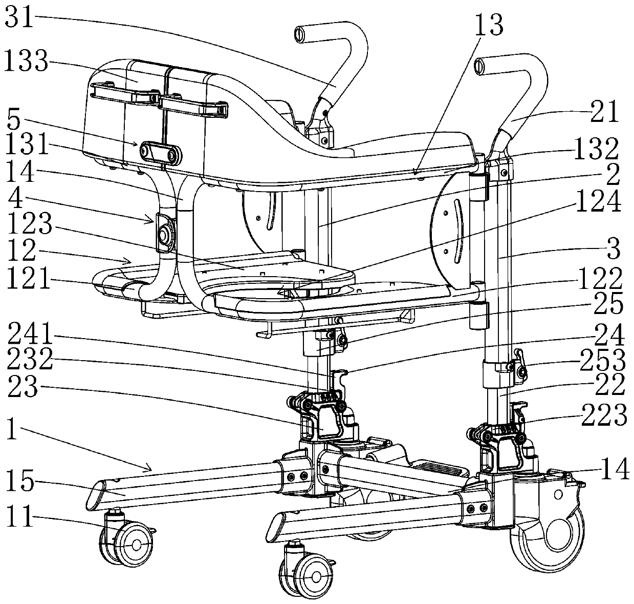
[0026] Example 1: as Figure 1-9 As shown in the figure, a foldable shift chair includes a base frame 1 and a plurality of rollers 11 arranged at the bottom of the base frame 1. A left pole 2 and a right pole 3 are arranged above one end of the base frame 1. A seat cushion frame 12 and a backrest frame 13 are arranged in sequence from bottom to top. The seat cushion frame 12 includes a left seat cushion frame 121 and a right seat cushion frame 122 which are opposite to each other. The front end is pivotally connected to the right upright rod 3 , the rear end of the left cushion frame 121 and the rear end of the right cushion frame 122 are enclosed with each other and locked by the cushion frame locking mechanism 4 , the inner side of the left cushion frame 121 and the inner side of the right cushion frame 122 are respectively provided with cushions 123. A circular cavity 124 is formed between the two seat cushions 123 in the middle. The backrest frame 13 includes a left backre...

Embodiment 2

[0036] Embodiment 2: The difference between this embodiment and Embodiment 1 is:

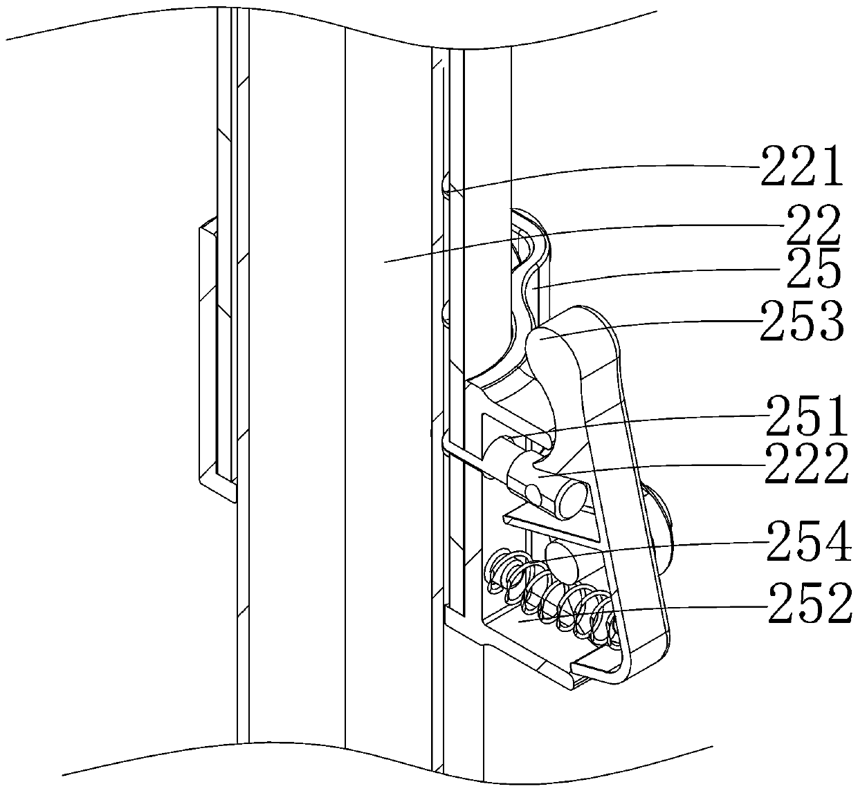
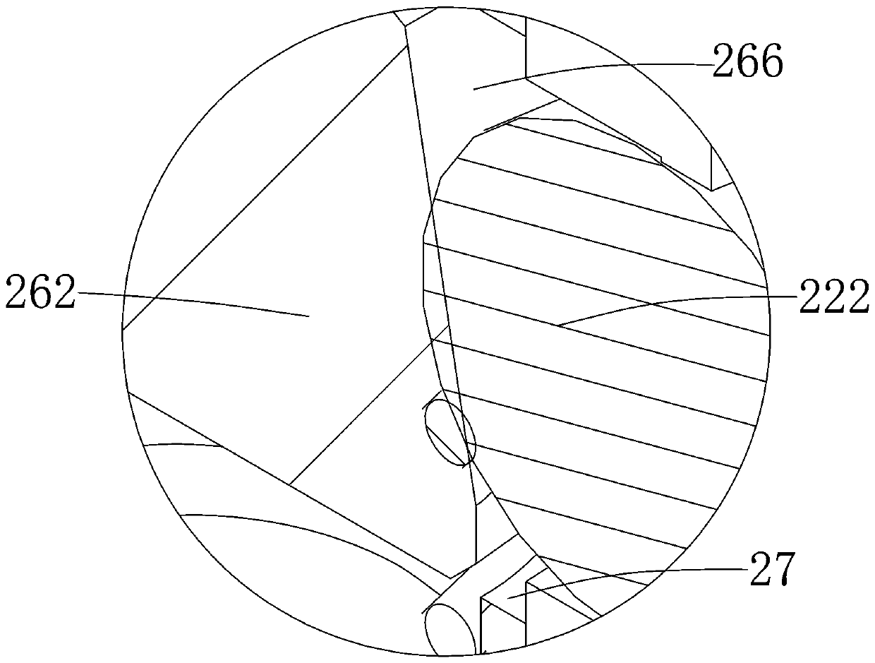
[0037] like Figure 3-5As shown, between the bottom frame 1 and the left pole 2 and the right pole 3, there is a flip locking mechanism for controlling the folding of the seat. The bottom of the inner tube 22 and the connecting portion 223 rotatably connected with one end of the connecting seat 23 and the locking handle 24 rotatably connected with the other end of the connecting seat 23, the locking member 222 is a spherical structure, and the tube wall of the left vertical rod 2 is provided with There is a fixed casing 26 and a through hole 27 that allows the locking member 222 to pass through a certain limiting hole 221. The fixed casing 26 is provided with a cavity 261 substantially parallel to the axis of the inner tube 22. The cavity 261 is provided with a limit post 262 that can move up and down in the cavity 261. A return spring 263 is arranged between the lower end of the limit post 262...


PUM

PropertyMeasurementUnit
Diameteraaaaaaaaaa

Abstract

The invention relates to a foldable shifting chair. The shifting chair comprises an underframe and a plurality of rollers arranged at the bottom of the underframe, a left upright rod and a right upright rod are arranged above one end of the underframe, a cushion frame and a backrest frame are sequentially arranged above the underframe from bottom to top, the cushion frame comprises a left cushionframe and a right cushion frame which are separated from each other, the front end of the left cushion frame is pivoted with the left upright rod, the front end of the right cushion frame is pivoted with the right upright rod, the rear end of the left cushion frame and the rear end of the right cushion frame are mutually enclosed and locked by a cushion frame locking mechanism, the inner side of the left cushion frame and inner side of the right cushion frame are each provided with a cushion, the backrest frame comprises a left backrest frame and a right backrest frame which are separated fromeach other, the front end of the left backrest frame is pivoted with the left vertical rod, the front end of the right backrest frame is pivoted with the right vertical rod, and the rear end of the left backrest frame and the rear end of the right backrest frame are mutually enclosed and locked by a backrest frame locking mechanism. The shifting chair is convenient to adjust, can be contracted and folded, and reduces space occupation.

Description

technical field [0001] The invention relates to a shift chair, in particular to a foldable shift chair. Background technique [0002] Some people with inconvenient lower limbs often use a shift chair for commuting. The shift chair includes a seat bracket, a seat is arranged on the seat bracket, and a moving wheel is arranged under the seat bracket. [0003] It is often very difficult for people with inconvenient lower limbs to sit on the lift chair, and it is very difficult to stand up. Therefore, the common lift chair is often very troublesome when using it, and it will cause secondary injury to the user if it is not careful. , causing great trouble to users. SUMMARY OF THE INVENTION [0004] The purpose of the present invention is to provide a foldable shift chair that is convenient to use, safe and reliable, and solves the problems of inconvenient use and easy to cause secondary injury in the prior art. [0005] The above technical purpose of the present invention is ...

Claims


Application Information

Patent Timeline
IPC IPC(8): A61G5/08A61G5/10
CPCA61G5/0883A61G5/10
Inventor 方政周斌
Owner ZHEJIANG INNUOVO REHABILITATION DEVICES CO LTD
Why Eureka
Try Eureka