Ultrasonic welding transducer universal adjustment device
A technology of ultrasonic welding and universal adjustment, which is applied in the field of earphone welding, can solve the problem that the transducer cannot realize universal adjustment, and achieve the effect of enhancing stability and reducing adverse effects
- Summary
- Abstract
- Description
- Claims
- Application Information
AI Technical Summary
Problems solved by technology
Method used
Image
Examples
Embodiment 1
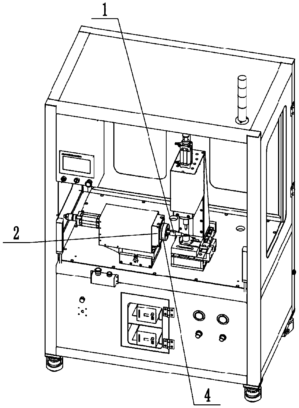
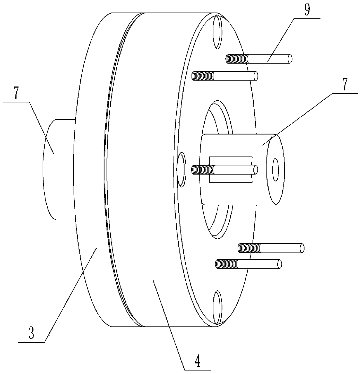
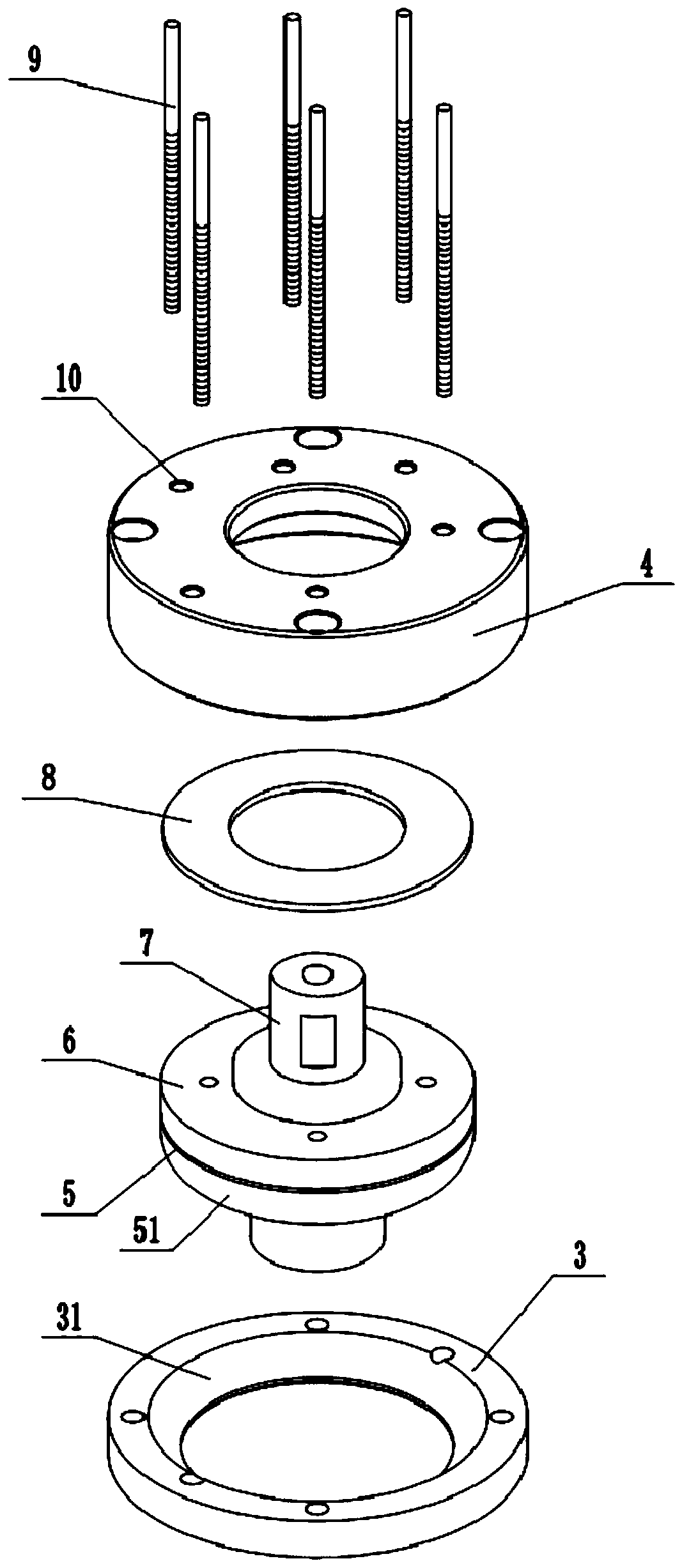
[0039] Ultrasonic welding transducer 7 universal adjustment device, combined with the attached figure 1 , attached figure 2 And attached image 3 As shown, it is mainly composed of an adjusting block mounting plate 2, an adjusting fixed cover 3, an adjusting fixed seat 4, a fixed ring, an adjusting pressing piece 8, and an adjusting mechanism. The adjusting block mounting plate 2 is fixedly connected with the output end of the cylinder, the adjusting fixed cover 3 is ring-shaped, and the adjusting fixed cover 3 and the adjusting block installing plate 2 are connected by bolts; the adjusting fixed cover 3 is provided with a central hole, and the axis of the central hole It coincides with the centerline of the adjusting and fixing cover 3 , and the part of the adjusting and fixing cover 3 near the central hole is formed with a first arc-shaped surface 31 .
[0040]The adjustment fixing seat 4 and the adjustment fixing cover 3 are fixed by bolts, and an installation space is f...
Embodiment 2
[0046] The difference between this embodiment and embodiment 1 is that: Figure 4 And attached Figure 5 As shown, the adjusting mechanism in the present embodiment is mainly composed of several jacks 14 and several second adjusting rods 11, and several jacks 14 are evenly distributed with the center of the adjusting holder 4 as the center of circle, and each jack 14 A plurality of limiting protruding rings 15 are welded or integrally formed along the axial direction of the socket 14 , and the limiting protruding rings 15 are equidistantly arranged, and a limiting groove 16 is formed between adjacent limiting protruding rings 15 . Each limiting protruding ring 15 is provided with a notch, and all the notches are distributed along the axial direction of the insertion hole 14 and are located on the same straight line, and all the notches form a slideway 17 . Several indicating points 18 for indicating the position of the slideway 17 are welded on the adjustment fixing seat 4, a...
Embodiment 3
[0055] The difference between this embodiment and Embodiment 1-2 is that: this embodiment also includes several pressing units for enhancing the stability of the first adjusting rod 9 / second adjusting rod 11, combined with the attached Figure 6 And attached Figure 7 As shown, the pressing unit is arranged on the adjustment fixing seat 4, and the pressing unit is mainly composed of a limiting piece 20, a rotating piece 21, and a spring ring 19. The limiting piece 20 is welded on the first adjusting rod 9 / second adjusting rod 11 On the side away from the adjustment pressing piece 8, the rotating piece 21 can rotate or move on the limit piece 20, and the rotating piece 21 is provided with a rotating hole, so that the first adjusting rod 9 / second adjusting rod 11 can be placed in the rotating hole. Inner rotation; and the limit piece 20 cannot pass through the rotation hole. One end of the spring ring 19 is welded on the rotating piece 21 , the other end of the spring ring 19 i...
PUM
 Abstract
Description
Claims
Application Information
 - R&D
- Intellectual Property
- Life Sciences
- Materials
- Tech Scout
- Unparalleled Data Quality
- Higher Quality Content
- 60% Fewer Hallucinations
Browse by: Latest US Patents, China's latest patents, Technical Efficacy Thesaurus, Application Domain, Technology Topic, Popular Technical Reports.
© 2025 PatSnap. All rights reserved.Legal|Privacy policy|Modern Slavery Act Transparency Statement|Sitemap|About US| Contact US: help@patsnap.com


