Vertical take-off and landing unmanned aerial vehicle and control method thereof

A technology of vertical take-off and landing of unmanned aerial vehicles, applied in the field of aviation aircraft, which can solve the problems of difficult control of unmanned aerial vehicles, small load, and increase the internal space of the aircraft, so as to eliminate the dihedral reflection effect, reduce the self-weight, and shrink the flight The effect of field size

Inactive Publication Date: 2020-07-17
SHENYANG AEROSPACE UNIVERSITY
View PDF10 Cites 3 Cited by
  • Summary
  • Abstract
  • Description
  • Claims
  • Application Information

AI Technical Summary

Problems solved by technology

[0005] Aiming at the problems existing in the prior art, the present invention provides a vertical take-off and landing unmanned aerial vehicle and its control method. When the unmanned aerial vehicle takes off and lands vertically, the lift fan engine and the tiltable turbofan engine provide lift and auxiliary balance , and control the attitude of the aircraft during the flight. At the same time, through the design of the aircraft structure and aerodynamic layout, the control difficulty of the aircraft is reduced, the internal space of the aircraft is increased, and the control difficulties and load capacity of the existing vertical take-off and landing unmanned aerial vehicles are effectively solved. Small problems, with the advantages of flexible and stable flight, wide application range and large load capacity

Method used


Image

  • Vertical take-off and landing unmanned aerial vehicle and control method thereof
  • Vertical take-off and landing unmanned aerial vehicle and control method thereof
  • Vertical take-off and landing unmanned aerial vehicle and control method thereof

Examples


Embodiment Construction

[0027] The present invention will be further described in detail below in conjunction with the accompanying drawings and specific embodiments.

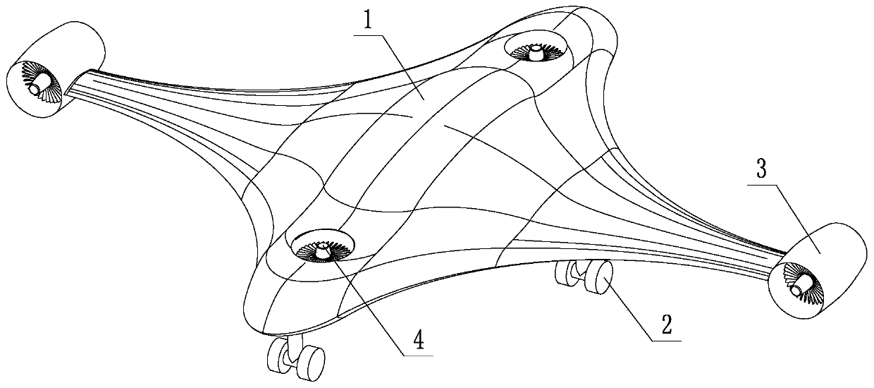
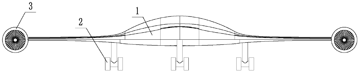
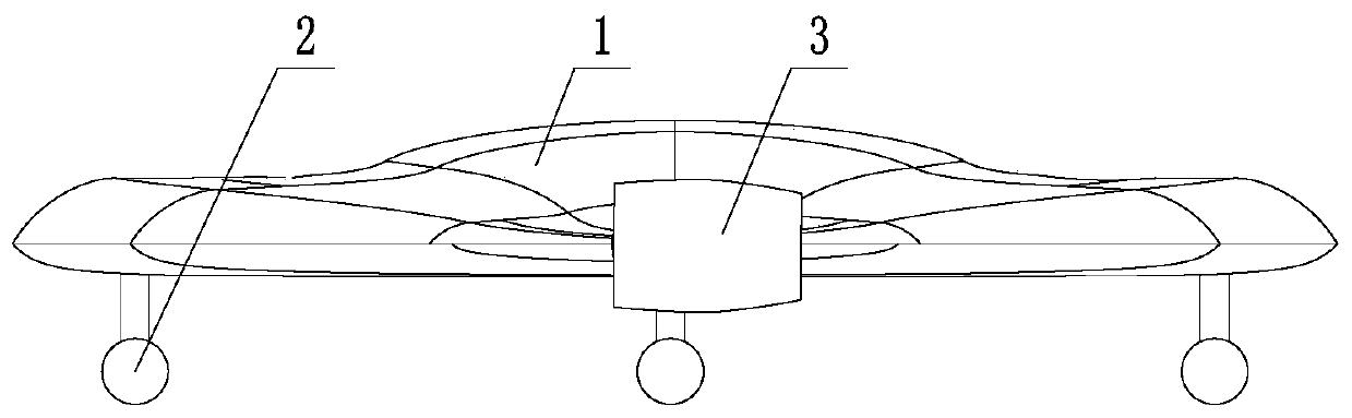
[0028] Such as Figure 1~4 As shown, a vertical take-off and landing UAV includes a wing-body fusion fuselage 1, a power system and a landing gear 2; structure, and the lateral wingspan of the wing-body fusion fuselage 1 is greater than the total longitudinal length; the power system includes a turbofan engine 3 and a lift fan engine 4; the number of the turbofan engines 3 is two, and the two turbofan engines 3 Symmetrically connected to the left and right sides of the wing-body fusion fuselage 1, the turbofan engine 3 is connected to the wing-body fusion fuselage 1 through a tilting transmission mechanism, and the turbofan engine 3 can perform 360° tilting and attitude adjustment by means of the tilting transmission mechanism When the turbofan engine 3 is tilted and adjusted, the thrust directions of the left and right turbofan engi...


PUM


Abstract

The invention discloses a vertical take-off and landing unmanned aerial vehicle and a control method thereof. The unmanned aerial vehicle comprises a wing body fusion fuselage, a power system and an undercarriage, and the power system comprises turbofan engines and lift fan engines; the wing body fusion fuselage adopts a structure which is symmetrical along the longitudinal axis and the transverseaxis of the overlooking plane; the two turbofan engines are symmetrically and externally connected to the left side and the right side of the wing body fusion fuselage, and the turbofan engines are connected with the wing body fusion fuselage through tilting transmission mechanisms; the two lift fan engines are symmetrically buried at the front end and the rear end of the wing body fusion fuselage. The control method comprises the following five stages of stage 1, vertical take-off and hovering, stage 2, hovering in the air and performing level flight, stage 3, level flight, stage 4, level flight-hovering in the air, and stage 5, hovering in the air and vertically landing. When the unmanned aerial vehicle takes off and lands vertically, lift force and auxiliary balance are provided by thefour engines, the aircraft is low in control difficulty and large in internal space of the fuselage, and the problems that an existing vertical take-off and landing unmanned aerial vehicle is difficult to control and small in load capacity are solved.

Description

technical field [0001] The invention belongs to the technical field of aviation aircraft, and in particular relates to a vertical take-off and landing unmanned aerial vehicle and a control method thereof. Background technique [0002] In recent years, UAV technology has developed rapidly. In terms of civilian use, UAVs have great application value in aerial photography, transportation, inspection, plant protection and other fields; in terms of military use, UAVs can be used for transportation, refueling, and reconnaissance. , strike and other combat missions. [0003] As a special type of UAV, the vertical take-off and landing UAV can take off and land at zero speed without opening up a special take-off and landing runway. Compared with conventional UAVs, the vertical take-off and landing UAV not only has It has the advantages of flexibility, convenient launch and recovery, good maneuverability, etc., and also has the general functions of conventional drones. Therefore, th...

Claims


Application Information

Patent Timeline
Patent Type & Authority Applications(China)
IPC IPC(8): B64C15/02B64C29/00B64D27/02G05D1/10
CPCB64C15/02B64C29/00B64D27/02G05D1/102B64U10/00B64U50/00
Inventor 杨靖宇张峻渤唐寅峰
Owner SHENYANG AEROSPACE UNIVERSITY
Why Eureka
Try Eureka