
Drainage system and equipment based on combined pipe network

A technology of confluence pipe and confluence system, applied in waterway system, sewer system, sewage removal, etc., can solve the problems of high processing pressure, waste of resources, increase cost, etc., to reduce the working state, avoid the drying of the river, and improve the service life. Effect

Pending Publication Date: 2020-07-17
WUHAN SHENGYU DRAINING SYST
View PDF0 Cites 0 Cited by
  • Summary
  • Abstract
  • Description
  • Claims
  • Application Information

AI Technical Summary

Problems solved by technology

[0005] The technical problem to be solved by the present invention is that in rainy days, the treatment pressure of the sewage treatment plant is very high and the operation is overloaded. Renovation of sewage pipes will inevitably increase the cost, and the technical defect that the river is prone to dry up in sunny days

Method used


Image

  • Drainage system and equipment based on combined pipe network
  • Drainage system and equipment based on combined pipe network
  • Drainage system and equipment based on combined pipe network

Examples


Embodiment 1

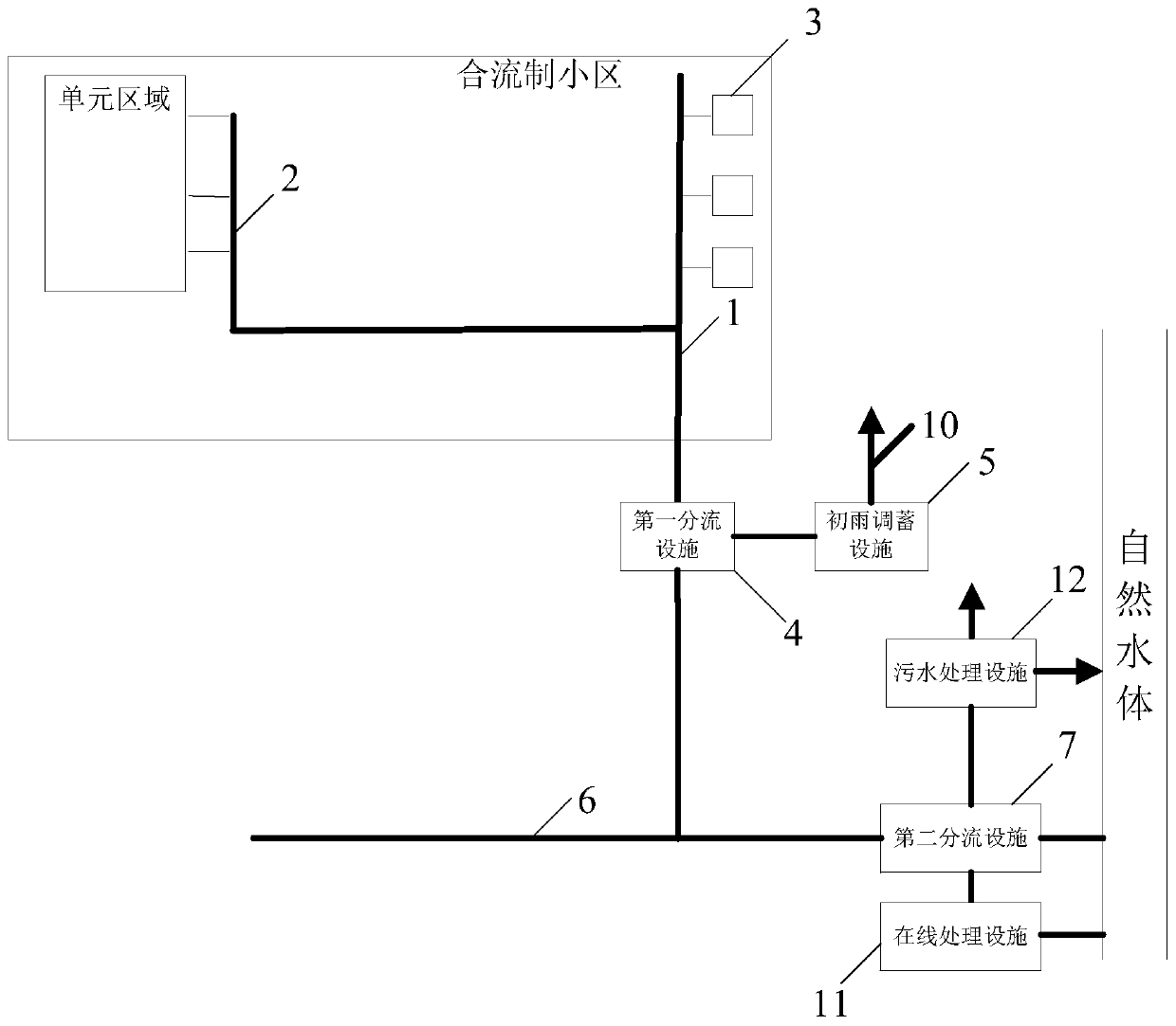
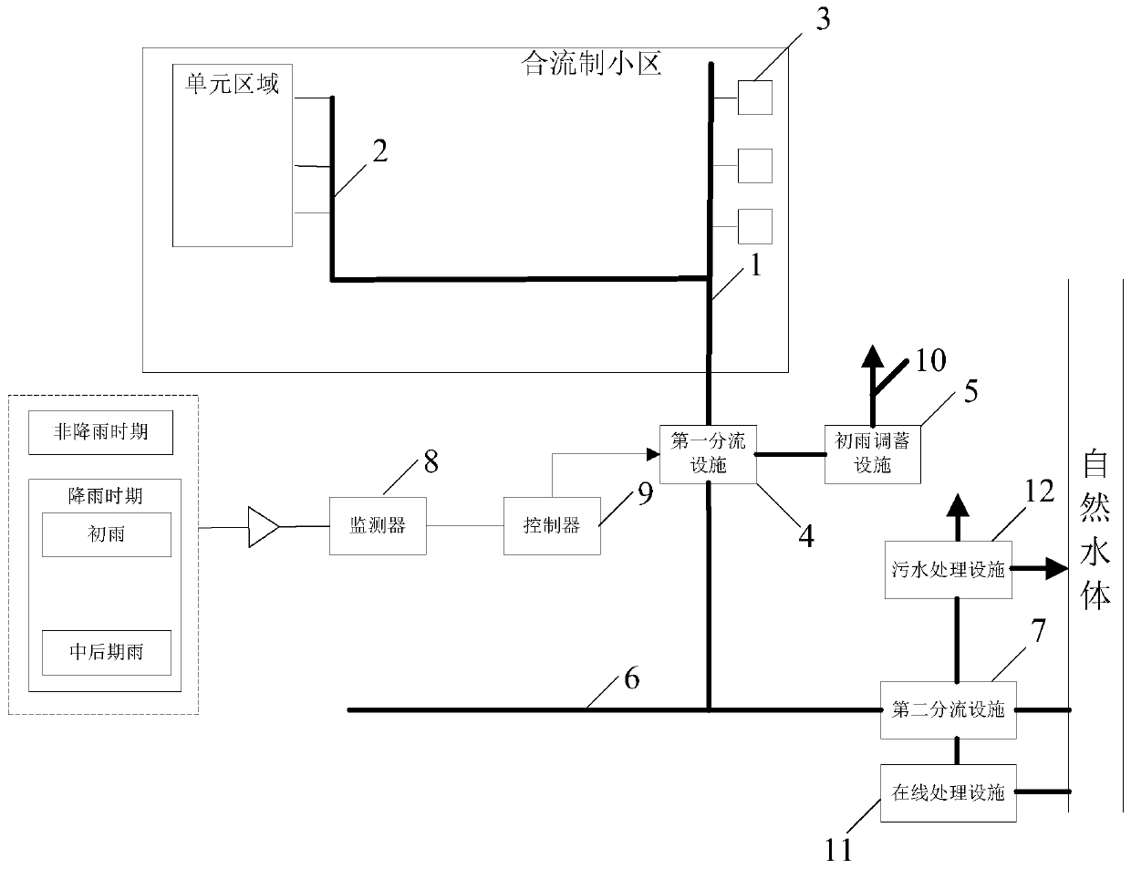
[0073] Please refer to figure 1 , is a schematic diagram of the overall structure of the drainage system based on the combined pipe network provided in Embodiment 1 of the present invention. The drainage system based on the combined pipe network specifically includes: a combined branch pipe 1, a sewage branch pipe 2, a rainwater outlet 3, a municipal merged pipe 6, The first diversion facility 4 , the first rain storage facility 5 , the second diversion facility 7 , the online treatment facility 11 and the sewage treatment facility 12 .

[0074] Among them, the confluence branch pipe 1, the sewage branch pipe 2, and the rainwater outlet 3 can all be set in the unit area, which is the area where sewage and rainwater need to be treated, and can be residential quarters, schools, administrative areas, etc. Of course, in the actual setting During the process, in order to connect with municipal pipelines, some branch pipes extend outside the unit area or municipal roads, which is also...

Embodiment 2

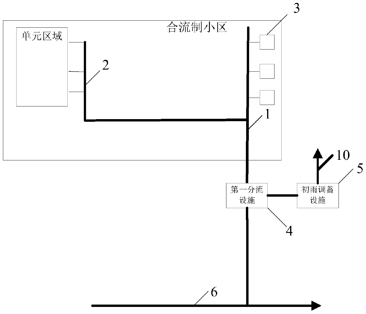
[0090] read on image 3, based on the same inventive concept, Embodiment 2 of the present invention provides a drainage device based on a combined pipe network, which is used for a municipal combined pipeline, the municipal combined pipeline includes a municipal combined pipe, and the equipment includes: a combined branch pipe 1, used to transport rainwater and / or sewage; the sewage branch pipe 2 is connected with the confluence branch pipe to transport the sewage into the confluence branch pipe; the rainwater outlet 3 is connected with the confluence branch pipe; the first The diversion facility 4 is connected with the confluence branch pipe and the municipal confluence pipe respectively, and is located at the downstream position of the confluence branch pipe; the initial rain regulation and storage facility 5 is connected with the first diversion facility; the second diversion facility 7. It communicates with the municipal confluence pipe and is located downstream of the mun...


PUM


Abstract

The invention provides a drainage system based on a combined pipe network. The drainage system comprises a confluence branch pipe; a sewage branch pipe communicated with the confluence branch pipe; agutter inlet communicated with the confluence branch pipe; a first shunting facility communicated with the confluence branch pipe and a municipal combined pipe respectively; an initial rainwater regulation and storage facility communicated with the first shunting facility; a second shunting facility communicated with the municipal combined pipe; and an online treatment facility and a sewage disposal facility which are respectively communicated with the second shunting facility. The treatment pressure of a treatment facility in the rainfall period is reduced, the service life of the treatment facility is prolonged, and resource waste is reduced; and the technical defect of river channel dryness caused by only treating and discharging the sewage is avoided in a non-rainfall period, so that the technical effect of timely supplying the river water is achieved.

Description

technical field [0001] The invention belongs to the technical field of municipal drainage, in particular to a drainage system and equipment based on a confluence pipe network. Background technique [0002] The city's municipal drainage system is mainly divided into combined drainage system and divergent drainage system. The earliest combined drainage system is to mix sewage, industrial wastewater and rainwater in the same pipe, and discharge them directly into the nearby water body without any treatment, which will easily cause serious pollution to the receiving water body. The diversion drainage system is a device that discharges domestic sewage, industrial wastewater and rainwater in two or more independent pipelines. [0003] At present, in the existing municipal drainage technology, in rainy days in most combined residential areas, the rainwater is divided into early rain and middle and late rain according to the time length method, water quality method, or liquid level...

Claims


Application Information

Patent Timeline
Patent Type & Authority Applications(China)
IPC IPC(8): E03F1/00E03F3/02E03F3/04
CPCE03F1/003E03F1/005E03F3/02E03F3/04E03F2201/10E03F2201/20
Inventor 周超
Owner WUHAN SHENGYU DRAINING SYST
Learn More