
Light anti-sliding fabricated comprehensive pipeline support and hanger and assembly method thereof

A comprehensive pipeline, anti-slip technology, applied in the direction of pipeline support, pipe/pipe joint/pipe fitting, rod connection, etc., can solve the failure of the connection between the fixed support and the vertical boom, the cross arm connection can not bear the pressure load, Problems such as loose bolt connections can shorten the assembly time, simplify the assembly process, and reduce the use of assembly equipment.

Pending Publication Date: 2020-07-17
江苏安赫智能装备科技有限公司
View PDF1 Cites 7 Cited by
  • Summary
  • Abstract
  • Description
  • Claims
  • Application Information

AI Technical Summary

Problems solved by technology

[0004] The technical solutions of the existing patent documents have the following technical defects: (1) The L-shaped corner connecting plates provided on the cross arm and the vertical suspender are all arranged at the corners of the inner wall of the cross arm, because the L-shaped corner connecting plates themselves are bent Formed by processing, when the cross-arm is subjected to a large load pressure, the two ends of the cross-arm are pressed down by the L-shaped corner connecting plates on both sides, and the L-shaped corner connecting plates on the bottom side are crushed and deformed, resulting in connection failure. The L-shaped corner connecting plates on the top side The tensile deformation of the corner connecting plate leads to connection failure, and the cross-arm connection cannot bear a large pressure load
When the bolts at the fixed support are used for a long time, the bolt connection will also be loose, resulting in failure of the connection between the fixed support and the vertical boom
The failure of the connection of each component causes the support and hanger to slip, which poses a safety hazard

Method used


Image

  • Light anti-sliding fabricated comprehensive pipeline support and hanger and assembly method thereof
  • Light anti-sliding fabricated comprehensive pipeline support and hanger and assembly method thereof
  • Light anti-sliding fabricated comprehensive pipeline support and hanger and assembly method thereof

Examples


Embodiment 1

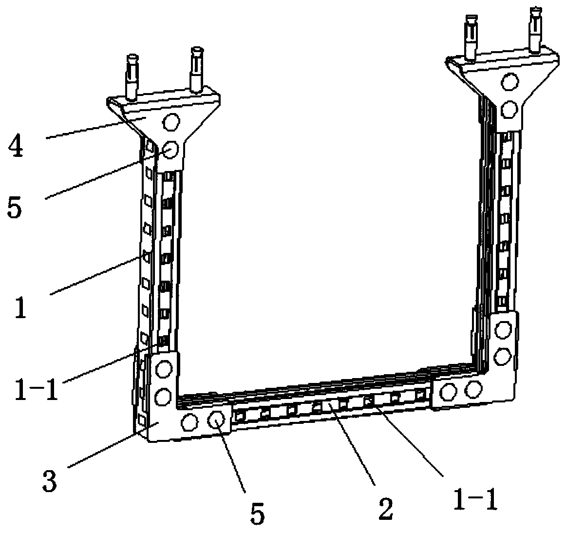
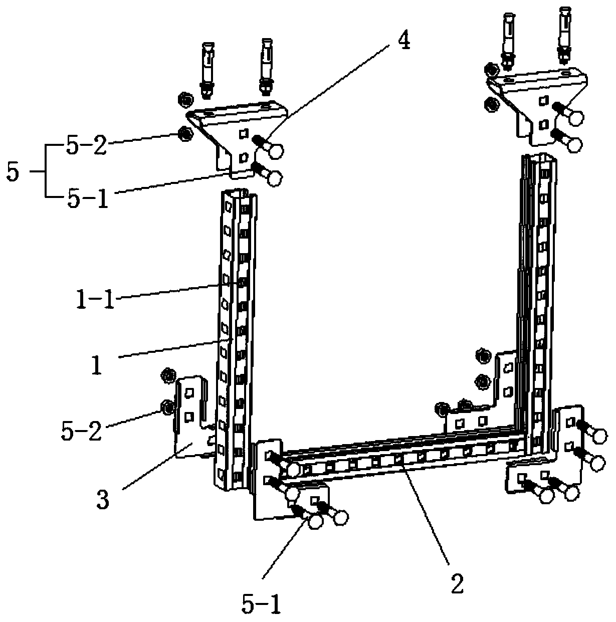
[0080] It can be seen from the accompanying drawings that it includes a column 1, a cross arm 2, a first corner connector 3, and a first base 4;

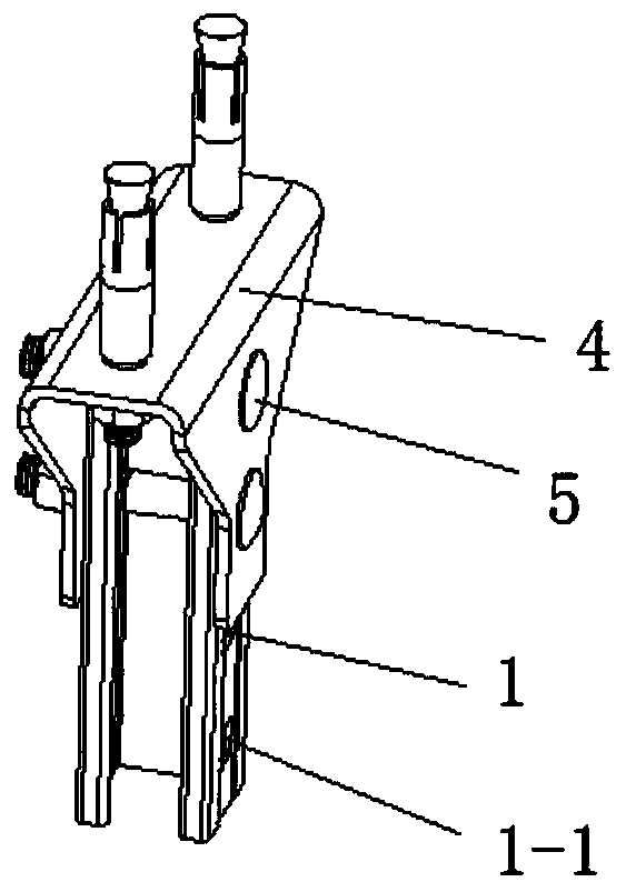
[0081] The number of the uprights 1 is two, and each upright 1 is arranged vertically at both ends of the cross arm 2 in a symmetrical arrangement; the three side walls of the uprights 1 and the cross arm 2 are provided with profile mounting holes 1-1; the first corner connector 3 is attached to the side wall of the column 1 and the cross arm 2, and one end of the column 1 on each side and the cross arm 2 is connected by a pair of the first corners The first base 4 is arranged on the top of the column 1 on each side, and is matched with the fastener 5 to realize locking and fixing.

[0082] Further, both the column 1 and the cross arm 2 are made of C-shaped inner angled channel steel.

[0083] Further, the profile mounting holes 1-1 provided on each of the uprights 1 and the cross arms 2 are arranged in an array, and each profile m...

Embodiment 2

[0097] It can be seen in conjunction with the accompanying drawings that the difference between embodiment 2 and embodiment 1 lies in the bolt 5-1, and the bolt 5-1 adopts a square neck bolt 5-1 of common length;

[0098] The number of fasteners 5 used in each of the first corner connectors 3 is four groups; the bolts 5-1 of each two groups of fasteners 5 pass through the first corner connection holes and a column of the first corner connector 3 respectively. 1 The mounting hole 1-1 of the profile on the single side wall is screwed with two sets of bolts 5-1 through two sets of nuts 5-2; the bolts 5-1 of each set of fasteners 5 penetrate through the first corner connector The first angle connection hole of 3, the profile installation hole 1-1 of the single side wall at one end of the cross arm 2, and are respectively threaded with two sets of bolts 5-1 by two sets of nuts 5-2;

[0099] The number of fasteners 5 used in each of the first bases 4 is four groups; the bolts 5-1 of...

Embodiment 3

[0101] It can be seen from the accompanying drawings that the difference between embodiment 3 and embodiment 1 lies in the first base 4, and embodiment 3 uses the second base 6 instead of the first base 4;

[0102] The second base 6 includes a second base cylinder 6-1 and a second base fin 6-2; the cross section of the second base cylinder 6-1 is in the shape of "匚", and the second base cylinder 6-1 The two sides of the wall are provided with a second base cylinder hole 6-1-1, and the number of the second base cylinder hole 6-1-1 on each side is two, in a square structure; the second base fin 6-1- 2. It is arranged on both sides of the end of the second base tube 6-1. The second base fins 6-2 are formed by mechanical bending and form an integral structure with the first base tube 4. The second base The surface of the second base fin 6-2 is provided with a second base fin hole 6-2-1;

[0103] The number of fasteners 5 used in each of the second base 6 is two groups; the bolts ...


PUM


Abstract

A light anti-sliding fabricated comprehensive pipeline support and hanger comprises stand columns, a cross arm, corner connectors and bases. The number of the stand columns is two, and the stand columns are vertically arranged at the two ends of the cross beam and arranged symmetrically. Profile mounting holes are formed in the three side walls of each of the stand columns and the cross beam. Thecorner connectors are attached to the side walls of the stand columns and the cross beam, and the corner connectors cooperate with fasteners to achieve locking and fixing. The bases are arranged at the top ends of the stand columns on the sides and cooperate with the fasteners to achieve locking and fixing. An opening of each profile mounting hole is square. The structure strength of the support connecting structure is higher, safety performance is high, the assembly process is simplified, use of assembly tools is reduced, the bolt assembly rate is increased, the assembly overall attractiveness is high, and use adaptability is high.

Description

technical field [0001] The invention relates to the field of building electromechanical installation engineering, in particular to a light-weight anti-slip assembled comprehensive pipeline support and hanger and an assembly method thereof. Background technique [0002] During the construction of engineering pipelines, it is usually necessary to lay various comprehensive pipelines. For some pipelines that need to be laid overhead, it is necessary to use pipeline supports and hangers for hoisting and fixing. In actual engineering cases, the support and hanger needs to meet the static load carrying the weight of the pipeline itself. During the installation process, due to human factors such as irregular operation of the workers, substandard construction technology, and unmanned monitoring of the construction quality, the support and hanger During the construction period, the connection strength of the structure is insufficient, and the connection of the support and hanger is re...

Claims


Application Information

Patent Timeline
Patent Type & Authority Applications(China)
IPC IPC(8): F16L3/00F16B7/18
CPCF16L3/00F16B7/18F16B7/182
Inventor 宋余贝赵鹏刘纪才
Owner 江苏安赫智能装备科技有限公司
Learn More