Standardized load-bearing support and hanger system and installation method thereof

A support and hanger system technology, applied in the direction of pipeline supports, electrical components, pipes/pipe joints/fittings, etc., can solve the problems of low standardization, inconvenient installation, poor versatility, etc., to achieve clear force, convenient installation and disassembly, Easy to adjust the effect

Inactive Publication Date: 2020-07-17
CHINA STATE CONSTRUCTION ENGINEERING CORPORATION +1
View PDF6 Cites 3 Cited by
  • Summary
  • Abstract
  • Description
  • Claims
  • Application Information

AI Technical Summary

Problems solved by technology

[0003] The purpose of the present invention is to provide a standardized load-bearing support and hanger system and its installation method, to solve the technical problems of the existing electromechanical pipeline load-bearing support and hanger with complex structure, inconvenient installation, low degree of standardization, and poor versatility

Method used


Image

  • Standardized load-bearing support and hanger system and installation method thereof
  • Standardized load-bearing support and hanger system and installation method thereof
  • Standardized load-bearing support and hanger system and installation method thereof

Examples


Embodiment 1

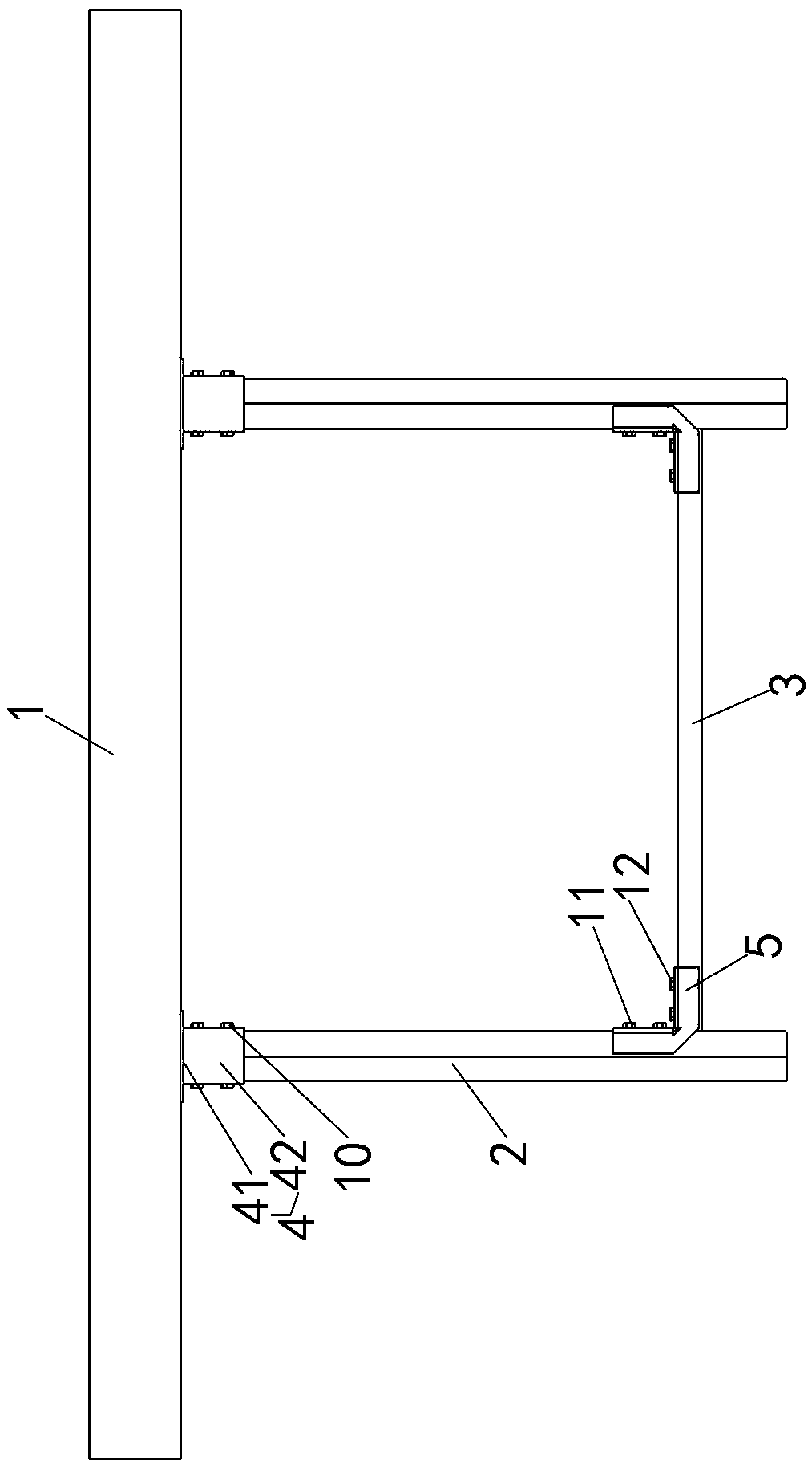
[0045] Embodiment one sees Figure 1-10 As shown, a standardized load-bearing support and hanger system includes a top beam 1 and a hanger fixed on the lower side of the top beam 1. The hanger includes two vertical arms 2 and two ends are fixedly connected between the two vertical arms 2. Between the crossarm 3.

[0046] The top of the vertical arm 2 is fixedly connected to the lower side of the hanger through the base 4 . Both ends of the cross arm 3 are fixedly connected to the vertical arm 2 through corner connection components.

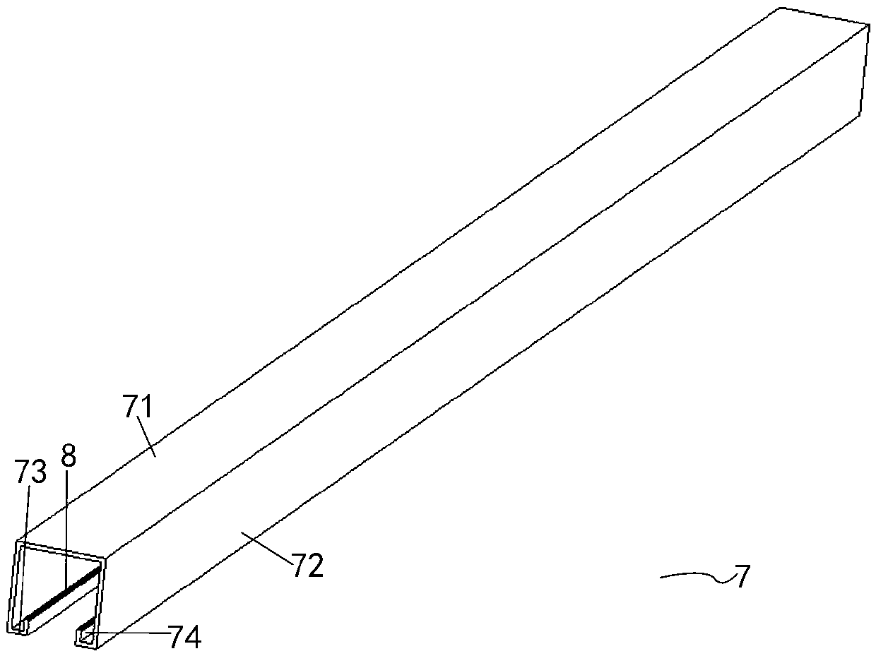
[0047] The vertical arm 2 or the cross arm 3 is a section of channel steel standard part 7 or is formed by connecting two sections of channel steel standard parts 7 through the extension connection assembly. The opening of the vertical arm 2 faces the cross arm 3, and the The opening of the load 3 faces upwards.

[0048] The channel steel standard part 7 includes a channel bottom plate 71, channel side plates 72 on both sides and channel side f...

Embodiment 2

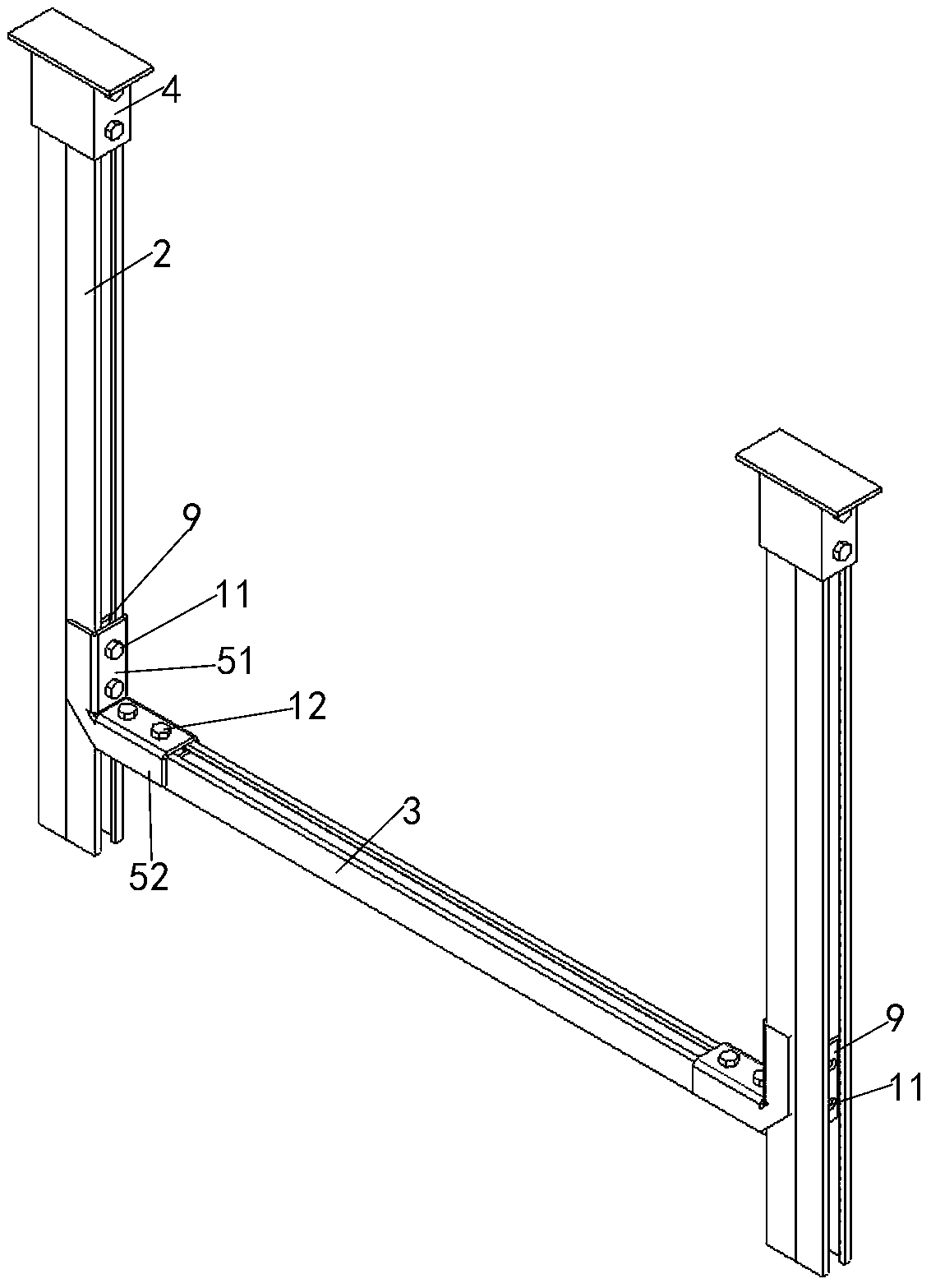
[0058] Embodiment two see Figure 11 As shown, the difference from the first embodiment is that the cross arm 3 is also double channel steel. see Figure 12 As shown, at this time, the corner connecting components are arranged symmetrically along the upper and lower sides of the cross arm 3, and if there are extended connecting components, they are symmetrically arranged in pairs along the upper and lower sides of the cross arm 3.

[0059] The installation method of this standardized load-bearing support and hanger system, the installation steps are as follows:

[0060] Step 1: Design the form of the vertical arm 2, the form of the corresponding base 4, the form of the cross arm 3, the number of corresponding corner connection components and whether the connection components need to be extended according to the force requirements, and when the connection components need to be extended number; and process the first connecting bolt 10, the second connecting bolt 11, the third ...


PUM


Abstract

The invention provides a standardized load-bearing support and hanger system and an installation method thereof. The standardized load-bearing support and hanger system comprises a top transverse beamand a hanging bracket. The hanging bracket comprises vertical arms and a cross arm. The tops of the vertical arms are fixedly connected to the lower side of the hanging bracket through bases. The twoends of the transverse arm are fixedly connected with the vertical arms through angle connection assemblies. The vertical arms or the transverse arm is formed by a section of channel steel standard component or formed by two sections of channel steel standard components through a lengthening connection assembly in a lengthening manner. Each channel steel standard component comprises a channel bottom plate, channel side plates and channel side flanges. A channel steel tooth is arranged on the top end face of each parallel flange. Each base comprises a horizontal connection plate and an outer sleeve. A tooth plate is inserted in each vertical arm. The outer sides of the tooth plates abut against the channel side flanges. Tooth plate clamping teeth and the channel steel teeth are clamped andfixed. Tooth plate connection holes and outer sleeve connection holes are right opposite and connected through first connection bolts. According to the standardized load-bearing support and hanger system and the installation method, standardized design is conducted for the load-bearing support and hanger system, and connection of all the standardized components is achieved through biting of the tooth plates and the channel steel teeth and then through bolt and connection piece fastening.

Description

technical field [0001] The invention belongs to the field of electromechanical installation, in particular to a standardized load-bearing support and hanger system and an installation method thereof. Background technique [0002] In the field of electromechanical installation, the number of electromechanical pipes in the electromechanical system of modern buildings is very large, the specifications and models are very complicated, and the use functions are also different. During the daily work of the electromechanical system, whether the pipeline has sufficient strength to fix the pipeline to the structure when it is operating under gravity is the key to the normal operation of the entire electromechanical system. How to arrange these piping systems reasonably and safely in buildings, hangers play a vital role. There are many forms of load-bearing supports and hangers, and the quality is different. There are generally technical problems such as complex structure, inconvenie...

Claims


Application Information

Patent Timeline
Patent Type & Authority Applications(China)
IPC IPC(8): F16L3/02H02G3/04
CPCF16L3/02H02G3/04
Inventor 史一剑林冰丛峻陈晓东郭敬孙喜亮
Owner CHINA STATE CONSTRUCTION ENGINEERING CORPORATION
Why Eureka
Try Eureka