Ergonomic tool handle enhancement

a tool handle and ergonomic technology, applied in the field of tool handle enhancement, can solve the problems of insufficient arm relief, heavy weight of power tools such as circular saws, and require an operator to apply additional strength, so as to improve the control of the tool, facilitate operation, and improve the effect of storage options

Inactive Publication Date: 2012-06-14
LEE SUNG K
View PDF13 Cites 14 Cited by
  • Summary
  • Abstract
  • Description
  • Claims
  • Application Information

AI Technical Summary

Benefits of technology

[0009]The above-identified drawbacks are solved by providing an ergonomic tool handle having an arm ring that is rotatable, but with built in resistance to rotation. With the present arm ring being rotatable by application of rotational force (torque), and temporarily fixable in various positions, the operator has an improved amount of control over the tool, ease of operation and more storage options.

Problems solved by technology

Power tools, such as circular saws, are typically heavy, and may require an operator to apply additional strength to achieve the desired precision and control when maneuvering the tool.
A disadvantage of the prior art is that the operator does not receive adequate relief from arm fatigue or assistance with maintaining adequate control over the tool from the various ring or loop attachments.

Method used


Image

  • Ergonomic tool handle enhancement
  • Ergonomic tool handle enhancement
  • Ergonomic tool handle enhancement

Examples


Embodiment Construction

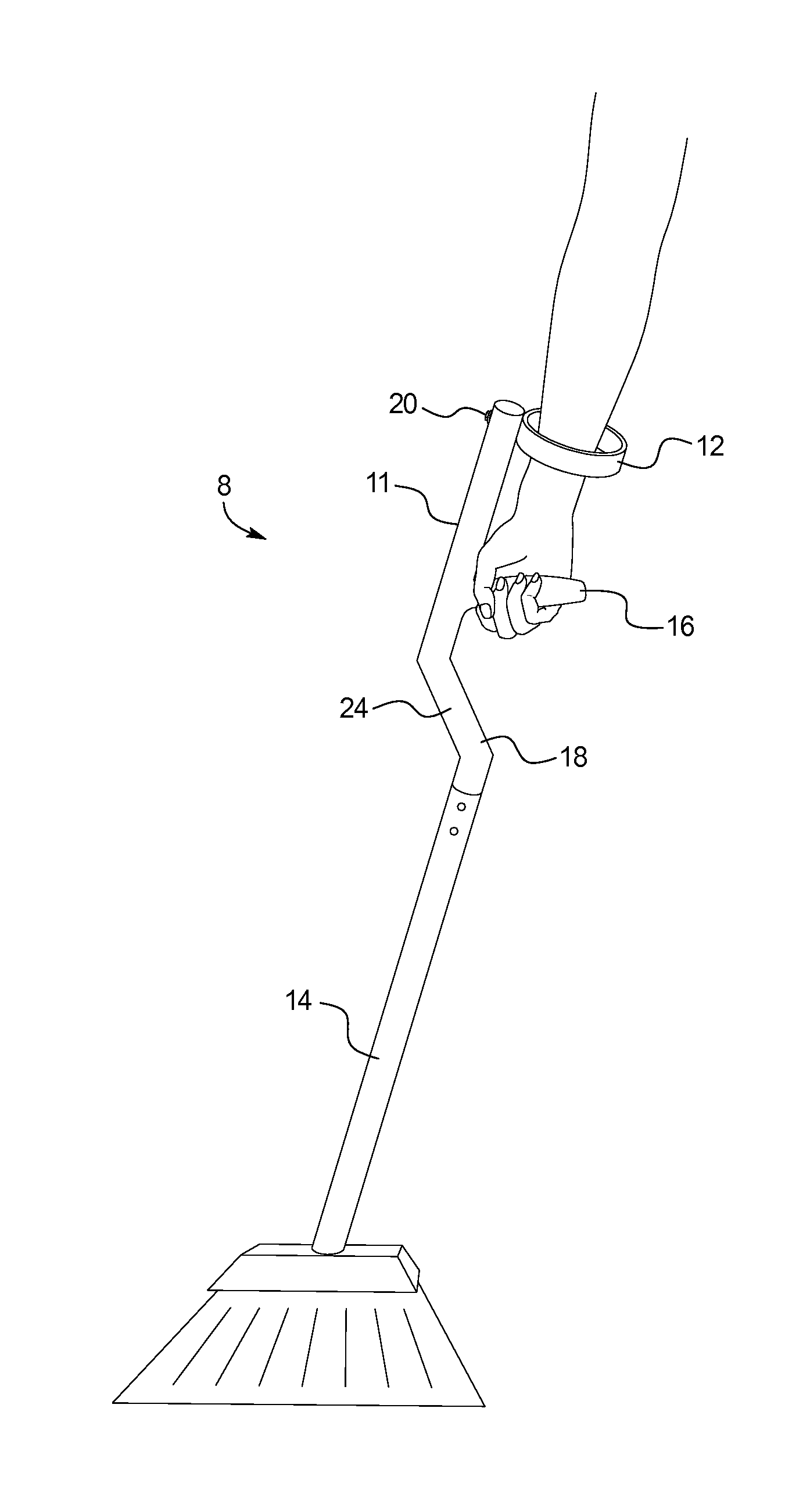
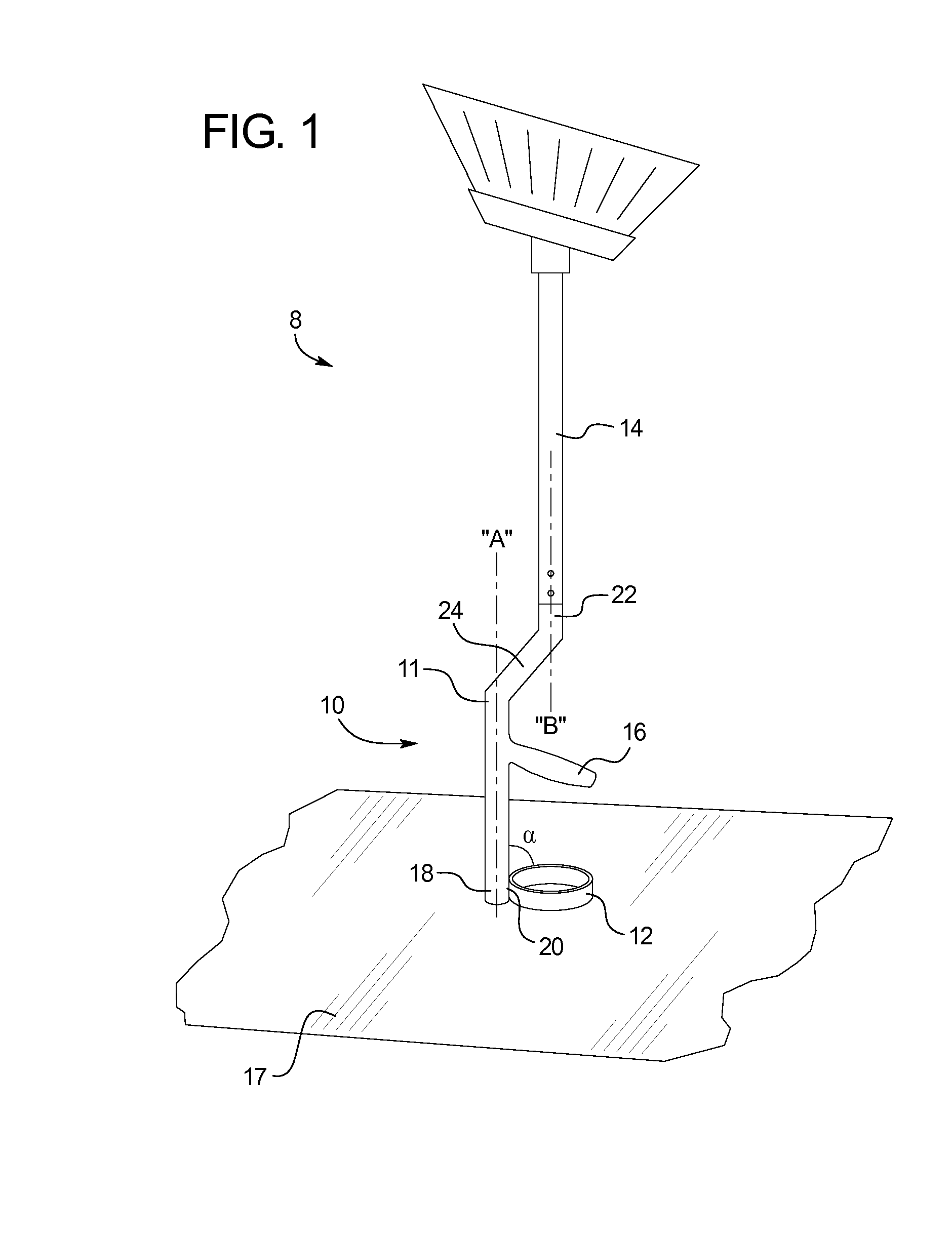
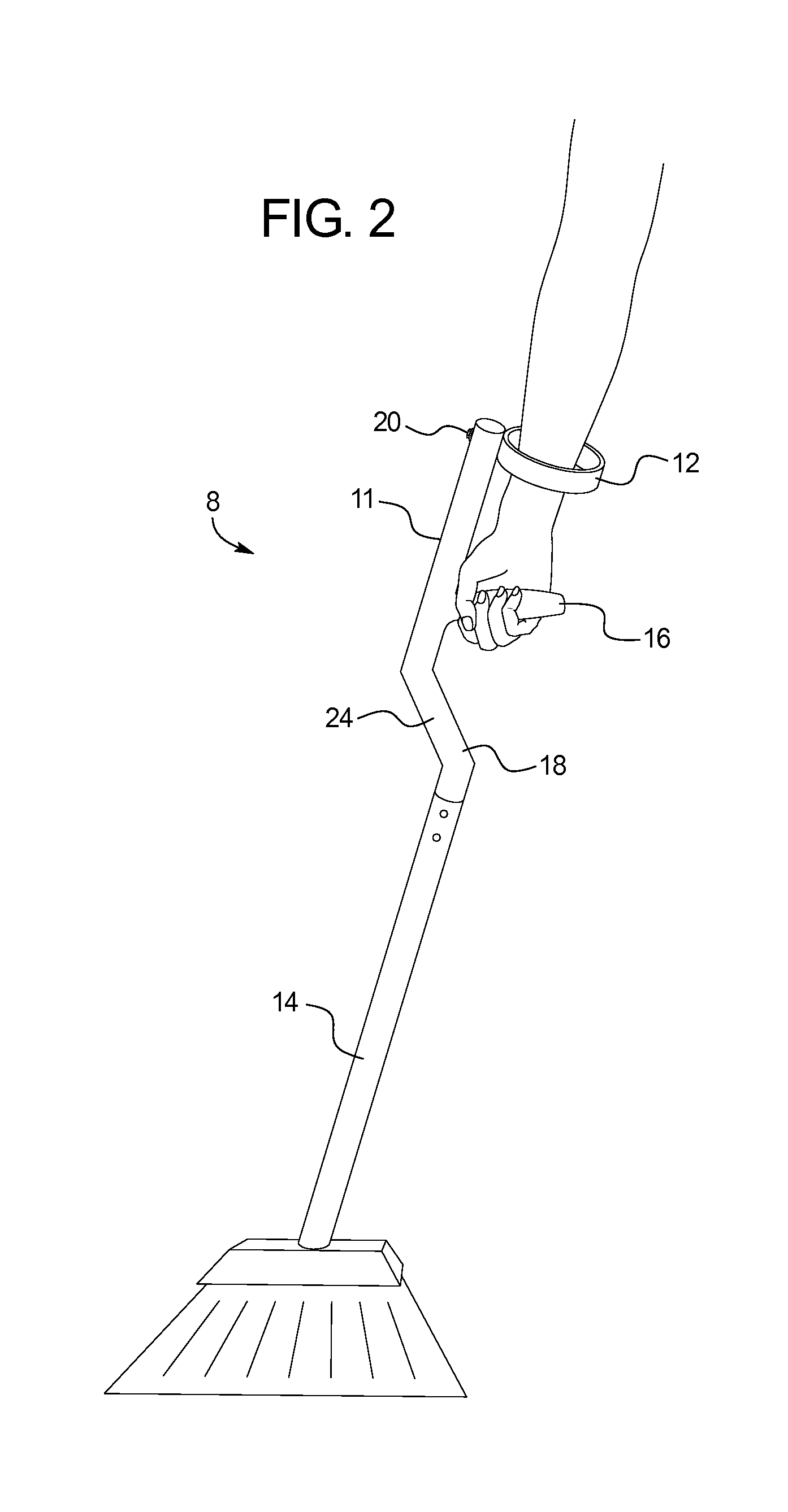
[0046]Referring to FIG. 1, a tool generally designated 8 is depicted as a broom, however other tools are contemplated, including but not limited to snow shovels, rakes, saws, hammers, lawn and hedge trimmers, scrapers and other powered or non-powered hand operated tools. An ergonomic tool handle, generally shown at 10, includes a single crossbar 11, and an arm ring 12 that is rotatably attached to the crossbar. A pole or shaft type tool handle member 14, such as that of a broom or rake, is connected to the ergonomic tool handle 10, which also preferably has a hand grip 16 that extends generally transversely from the crossbar 11. The tool 8 is shown inverted from its conventional use position and is supported on a substrate 17. The crossbar 11 includes a free end 18, where the arm ring 12 is rotatably disposed at a point of attachment 20 (best seen in FIG. 3), and an opposite working end 22 that is associated with the tool handle member 14.

[0047]In a preferred embodiment, the hand gr...


PUM


Abstract

A tool handle including: a body configured to receive a handle of a tool; a hand grip extending approximately perpendicular from the body; and an arm ring rotatably disposed on the body, wherein the arm ring is adapted to be placed in at least two positions, a first position in which the arm ring is generally perpendicular to the hand grip such that a user may place the user's forearm through the arm ring to grasp the hand grip and a second position in which the arm ring is generally parallel to the hand grip so as to minimize the width of the tool handle.

Description

CROSS-REFERENCE TO RELATED APPLICATIONS [0001]This application incorporates by reference and claims priority to U.S. Provisional Patent Application No. 61 / 422,811, filed Dec. 14, 2010 and U.S. Provisional Patent Application No. 61 / 524,314, filed on Aug. 16, 2011.BACKGROUND OF THE INVENTION[0002]The present invention relates generally to a tool handle enhancement for various tools including brooms, shovels, rakes and power tools. More specifically, an ergonomic tool handle is provided to ease strain on the operator's wrist, elbow and / or back.[0003]Conventional brooms, rakes or similar tools, especially those having elongated, pole type handles are operated by maneuvering the tool using the wrists, arms, shoulders and back. For example, a broom operator does this type of work to sweep debris into a pile. Areas which are difficult to access, such as under a table or corners, may involve additional use of the legs, back and other muscles to provide leverage and support. Power tools, suc...

Claims


Application Information

Patent Timeline
Patent Type & Authority Applications(United States)
IPC IPC(8): B25G1/10
CPCB25G1/102A01B1/00Y10T16/4713A47L13/08Y10S16/901A01B1/22
Inventor LEE, SUNG K.
Owner LEE SUNG K
Why Eureka
Try Eureka