Rotary/fixed wing aircraft

a fixed-wing aircraft and rotary technology, applied in the field of hybrid aircraft, can solve the problems of stalling of the retreating rotor blade in high-speed forward flight, inability to provide control or lift to the aircraft, and failure to achieve the development of functional, single-rotor hybrid aircraft capable of carrying a plurality of passengers with a substantial payload

Inactive Publication Date: 2004-06-17
PICA BRET D
View PDF10 Cites 15 Cited by
  • Summary
  • Abstract
  • Description
  • Claims
  • Application Information

AI Technical Summary

Problems solved by technology

A functional, preferably single rotor, hybrid aircraft capable of carrying a plurality of passengers with a substantial payload has not been successfully developed.
The primary barrier to high speed helicopter flight is that the retreating rotor blade in high speed forward flight will stall because its effective airspeed approaches zero at a set rotational velocity.
There will be a period of time when the retreating rotor blade cannot provide any control or lift to the aircraft because of its near zero relative airspeed.
Therefore, a larger surface area during rotational flight is detrimental to efficiency and control responsiveness.
The annulus is attached to the aircraft and acts as a fixed wing and does not provide for rotation of the wing.
This configuration is not suited for rotation due to the eccentricity of the s

Method used


Image

  • Rotary/fixed wing aircraft
  • Rotary/fixed wing aircraft
  • Rotary/fixed wing aircraft

Examples


Embodiment Construction

[0041] The drawing figures are intended to illustrate the general manner of design and construction of the invention, and are not to scale. References, in the description and in the claims, to left, right, front, back and the like are used for descriptive purposes, and should not be misinterpreted as to limit the scope of the claims or invention. It shall be understood that the embodiment of the invention as described is capable of operation in other orientations than described or shown.

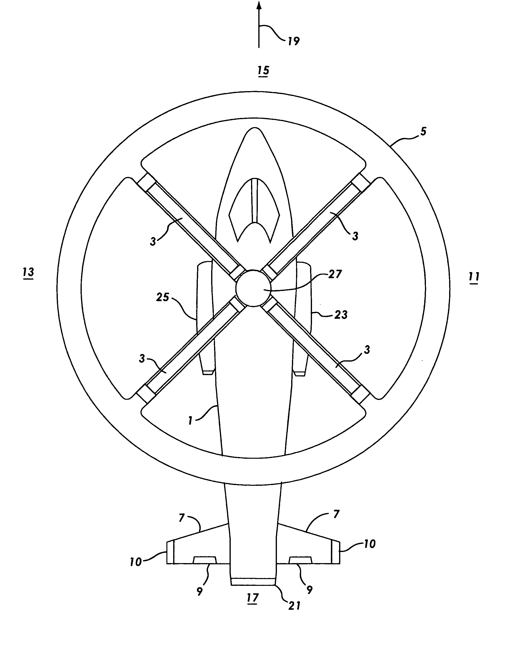
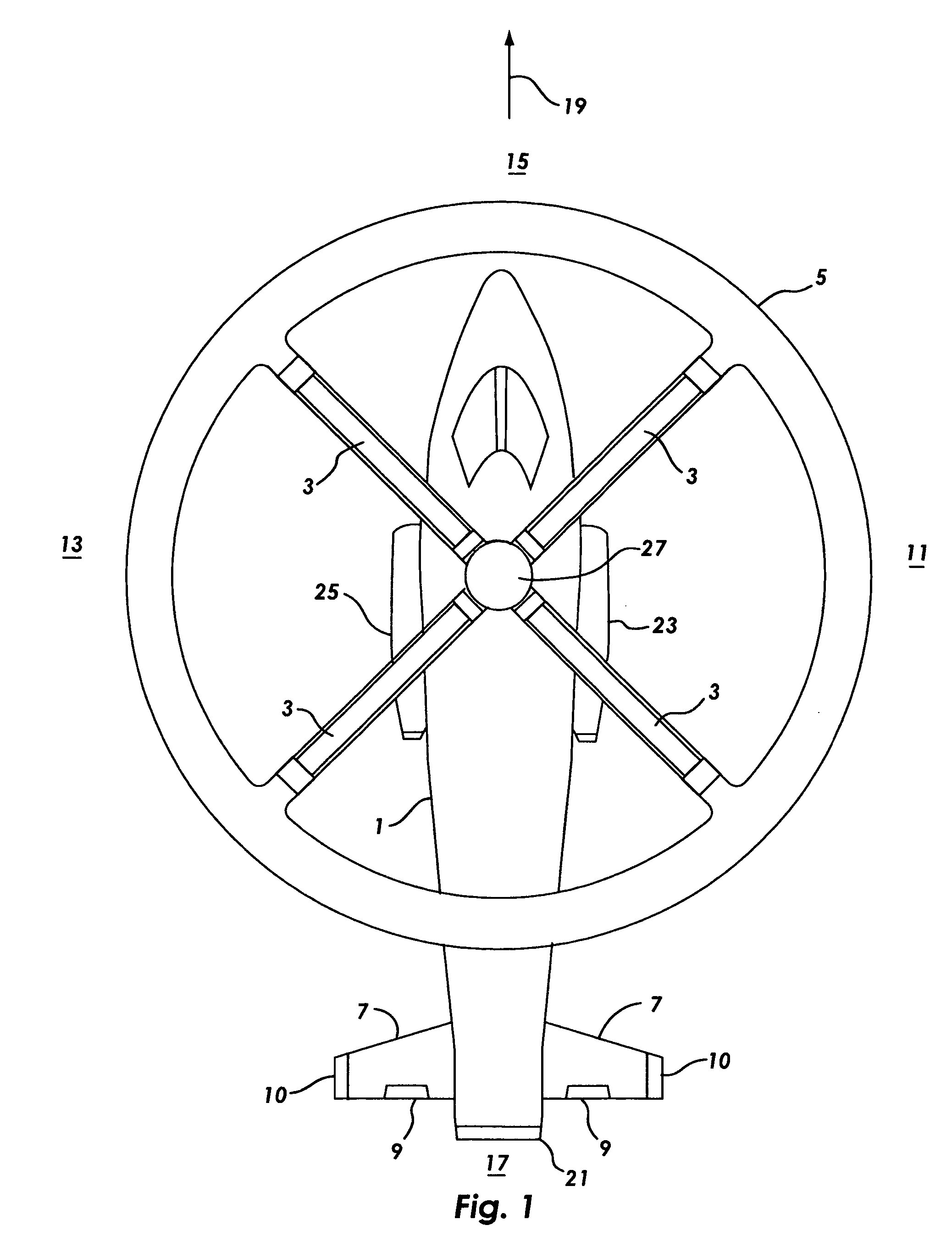
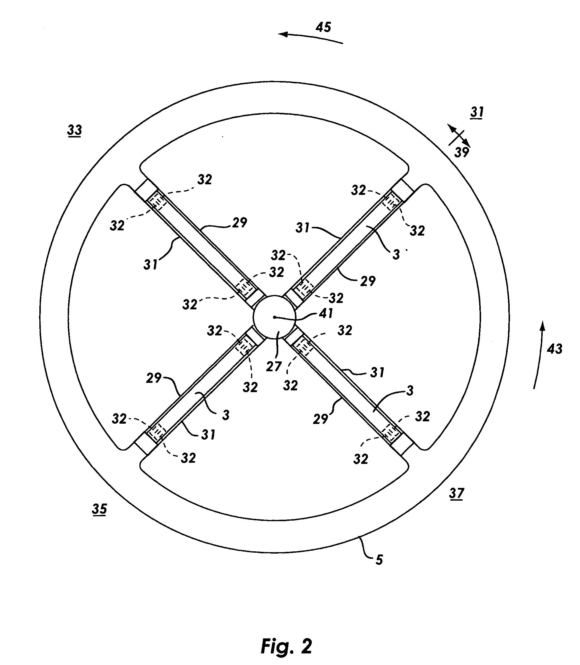
[0042] FIG. 1 illustrates an aircraft fuselage 1 equipped with an embodiment of the present invention comprised of rotor blades 3 of which any single rotor blade extends from rotating hub 27 to an annular wing 5. A horizontal stabilizer 7, elevators 9, and vertical stabilizers 10 on the fuselage 1 are common fixed wing aircraft embodiments. Aircraft directional references are right 11, left 13, nose 15, and tail 17. A longitudinal axis 19 extends lengthwise through the fuselage 1. A fan tail 21 or ve...


PUM


Abstract

A rotor system that allows an aircraft to operate as a helicopter and as an airplane is disclosed. The invention incorporates an annular airfoil attached at the tips of the rotor blades. The rotor system stops and is secured from rotation for operation at high forward speeds. The annulus acts as the primary lifting surface in airplane mode at high speed. The rotor blades incorporate leading and trailing edge flaps for control in transitional and fixed wing flight modes.

Description

DESCRIPTION[0001] This application claims priority of provisional application Serial No. 60 / 386031, entitled "Rotary / Fixed Wing Aircraft" filed on Jun. 4, 2002, which is incorporated herein by this reference.Related Art[0002] U.S. Pat. No. 2,455,866 to Kaman describes rotor servo flaps.[0003] U.S. Pat. No. 3,253,805 to Taylor describes an aircraft with a substantially annular wing.[0004] U.S. Pat. No. 4,560,358 to Adler describes a gliding ring with a separator lip.[0005] U.S. Pat. No. 4,711,415 to Binden describes an X-Wing aircraft.[0006] U.S. Pat. No. 6,161,799 to Nyhus describes a rotor blade lock system for rotary / wing aircraft.[0007] U.S. Pat. No. 6,170,779 to Nyhus describes a rotor pitch lock system for rotary / wing aircraft[0008] U.S. Pat. No. 6,231,013 to Jaenker describes an airfoil member with a piezoelectrically actuated servo-flap.[0009] "Solid State Rotor Tested", Paul Proctor, Aviation Week and Space Technology, Apr. 15, 1996 p. 46, is a relevant reference regarding a...

Claims


Application Information

Patent Timeline
IPC IPC(8): B64C27/22B64C27/32
CPCB64C27/32B64C27/22
Inventor PICA, BRET D.
Owner PICA BRET D
Why Eureka
Try Eureka