Laser radar window dirt detection method, device and system and medium
A technology of lidar and detection method, applied in image data processing, instrument, character and pattern recognition, etc., can solve problems such as increased cost and complex structure
- Summary
- Abstract
- Description
- Claims
- Application Information
AI Technical Summary
Problems solved by technology
Method used
Image

Examples
Embodiment 1
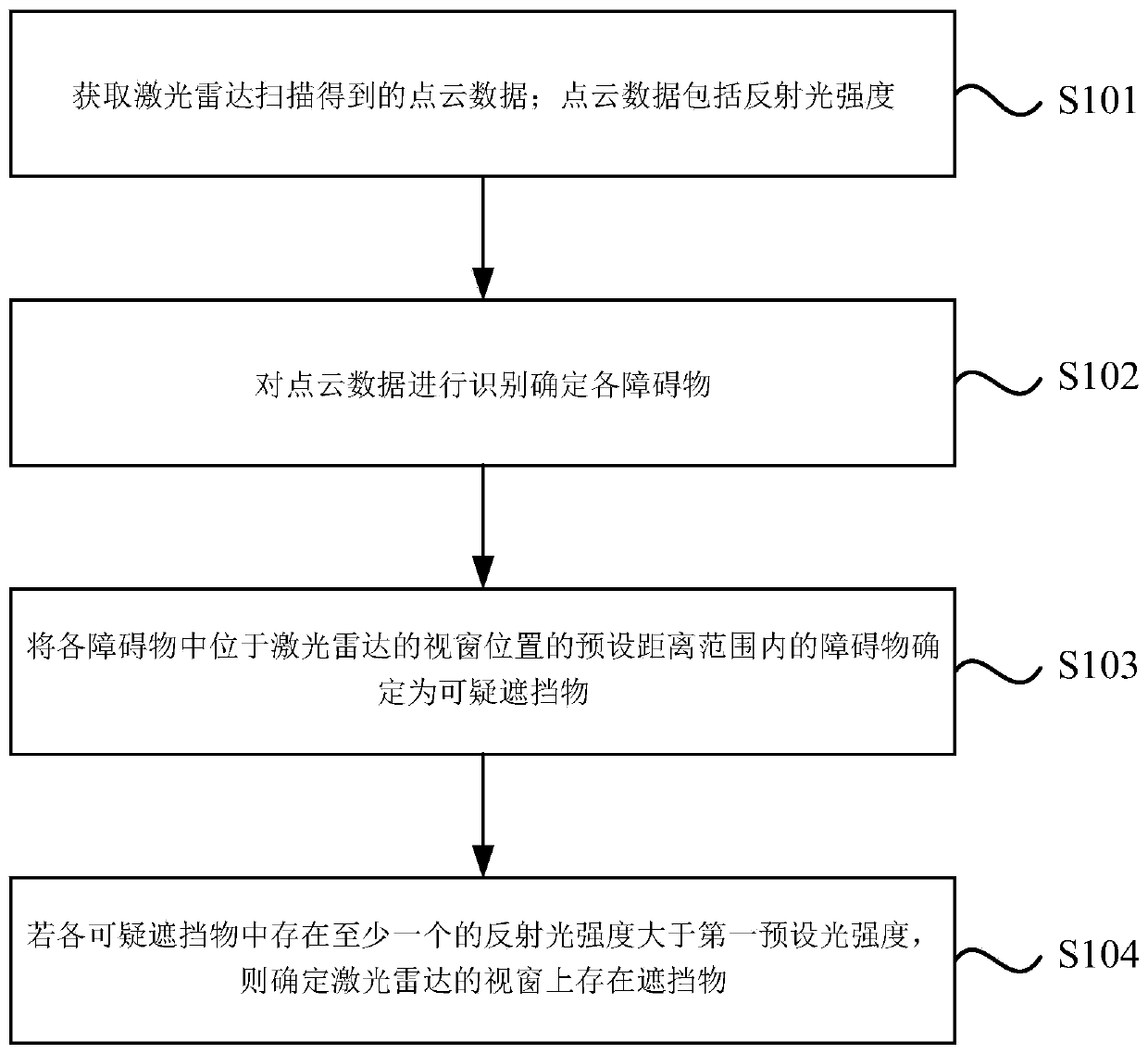
[0029] figure 1 It is a flow chart of a method for detecting dirt on a LiDAR window in Embodiment 1 of the present invention. This embodiment is applicable to the detection of dirt on the LiDAR window using point cloud data collected by LiDAR. The method can be executed by the cleaning control device in the laser radar cleaning system of the embodiment of the present invention, and the processing device can be implemented by software and / or hardware. Such as figure 1 As shown, the method specifically includes the following steps:
[0030] S101. Obtain point cloud data obtained by laser radar scanning; the point cloud data includes reflected light intensity.
[0031] Wherein, the point cloud data can be a collection of three-dimensional coordinate vectors recorded in the form of point clouds when the lidar scans the scene where it is located, and each three-dimensional coordinate vector can be represented by (x, y, z). The point cloud data may include multiple data points, a...
Embodiment 2
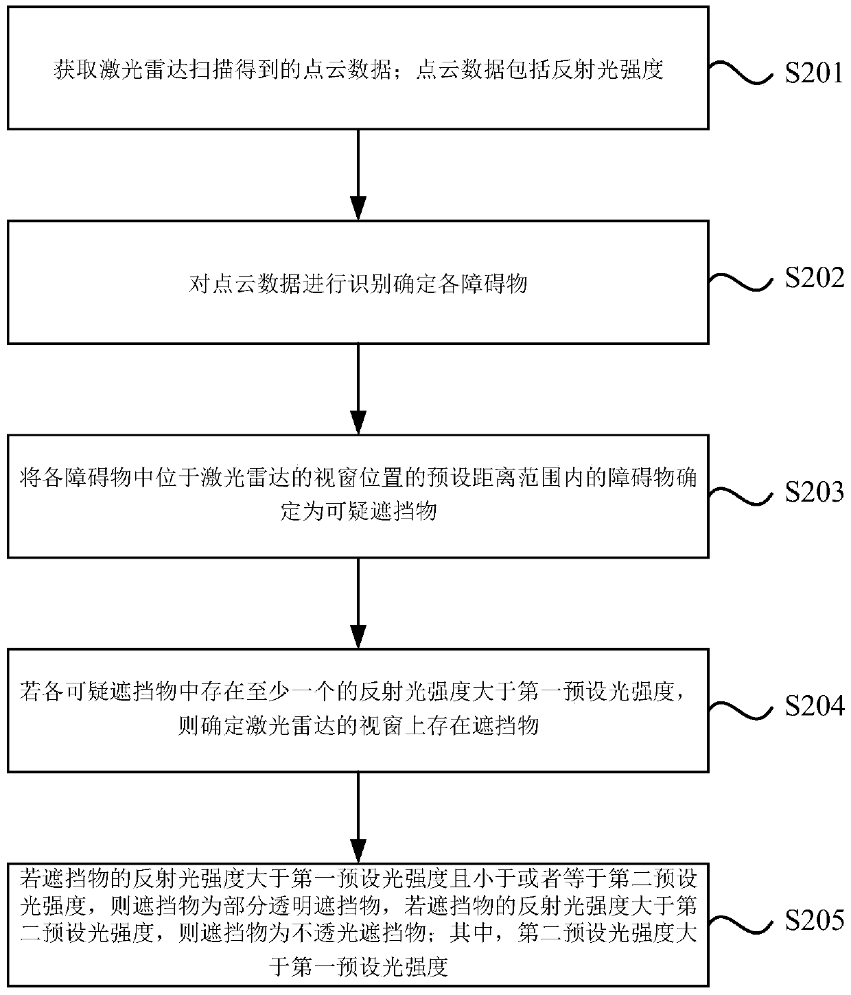
[0053] figure 2 It is a flow chart of a detection method for lidar window dirt in Embodiment 2 of the present invention. This embodiment is based on the above-mentioned embodiment, and further optimization is carried out. Specifically, it is given how to detect the dirt according to the reflected light intensity of the occluder. Introduction to judging the type of occlusion. Such as figure 2 As shown, the operation process includes the following steps:
[0054] S201. Obtain point cloud data obtained by laser radar scanning; the point cloud data includes reflected light intensity.
[0055] S202. Identifying the point cloud data to determine each obstacle.
[0056] S203. Among the obstacles, obstacles located within a preset distance range of the lidar window position are determined as suspicious obstructions.
[0057] S204. If the reflected light intensity of at least one of the suspicious obstructions is greater than the first preset light intensity, determine that there...
Embodiment 3
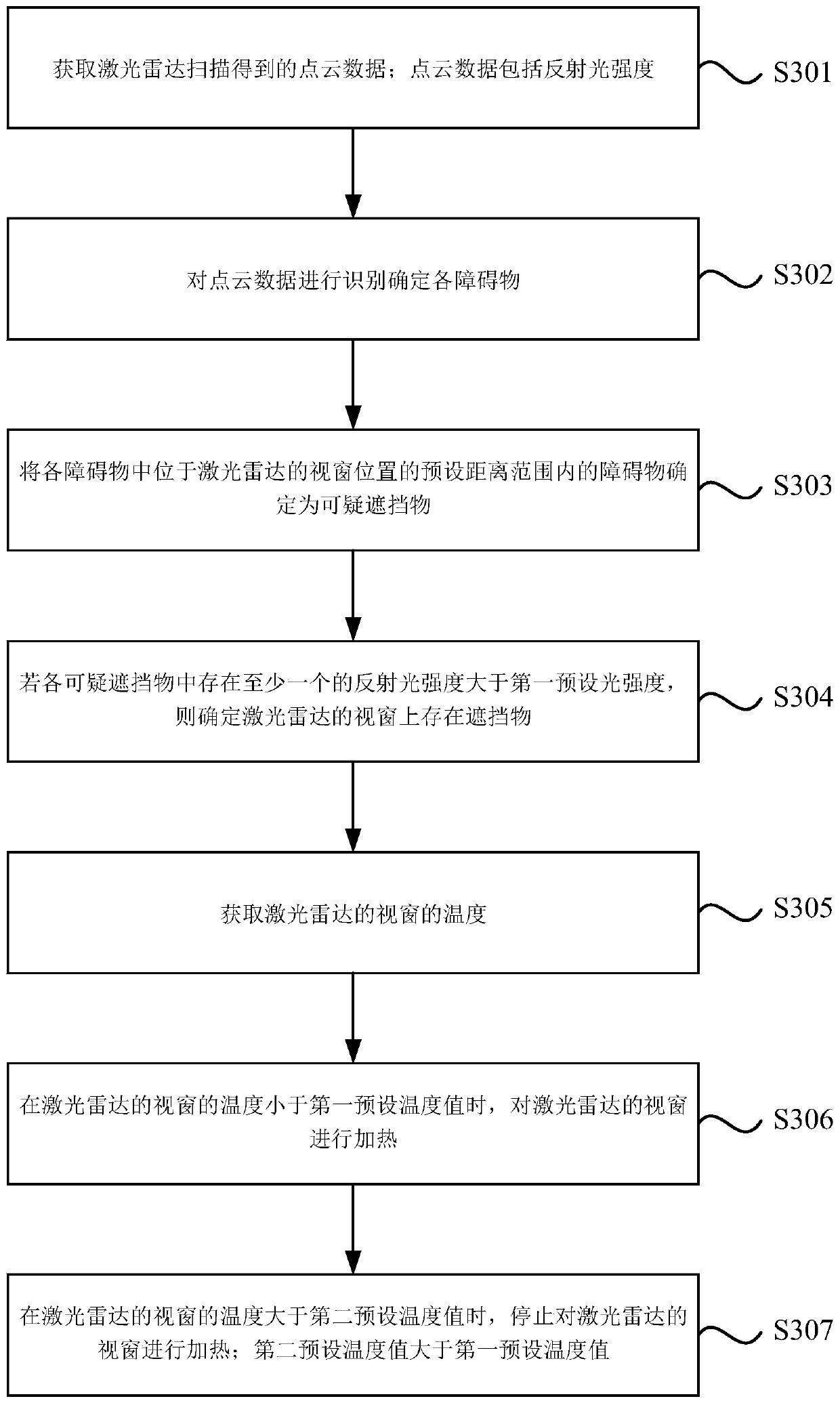
[0066] image 3 It is a flow chart of a method for detecting dirt on the lidar window in Embodiment 3 of the present invention. This embodiment is based on the above-mentioned embodiment and has been further optimized. It specifically provides how to automatically Introduction to heating and cleaning of shelters. Such as image 3 As shown, the operation process includes the following steps:
[0067] S301. Obtain point cloud data obtained by laser radar scanning; the point cloud data includes reflected light intensity.
[0068] S302. Identifying the point cloud data to determine each obstacle.
[0069] S303. Determine, among the obstacles, the obstacles located within a preset distance range of the lidar window position as suspicious obstructions.
[0070] S304. If the reflected light intensity of at least one of the suspicious obstructions is greater than the first preset light intensity, determine that there is an obstruction on the lidar window.
[0071] S305. Obtain th...
PUM
 Abstract
Description
Claims
Application Information
 - R&D
- Intellectual Property
- Life Sciences
- Materials
- Tech Scout
- Unparalleled Data Quality
- Higher Quality Content
- 60% Fewer Hallucinations
Browse by: Latest US Patents, China's latest patents, Technical Efficacy Thesaurus, Application Domain, Technology Topic, Popular Technical Reports.
© 2025 PatSnap. All rights reserved.Legal|Privacy policy|Modern Slavery Act Transparency Statement|Sitemap|About US| Contact US: help@patsnap.com