Assembling device and assembling method for assembling magnetic strip and magnetic strip frame
An assembly device and assembly method technology, applied in magnetic core manufacturing, inductor/transformer/magnet manufacturing, electrical components, etc., can solve the problems of high labor cost, high labor intensity, low production efficiency, etc., to reduce labor intensity, improve Productivity and workload reduction effect
- Summary
- Abstract
- Description
- Claims
- Application Information
AI Technical Summary
Problems solved by technology
Method used
Image

Examples
Embodiment Construction
[0034] The present invention will be further described below in conjunction with accompanying drawing.
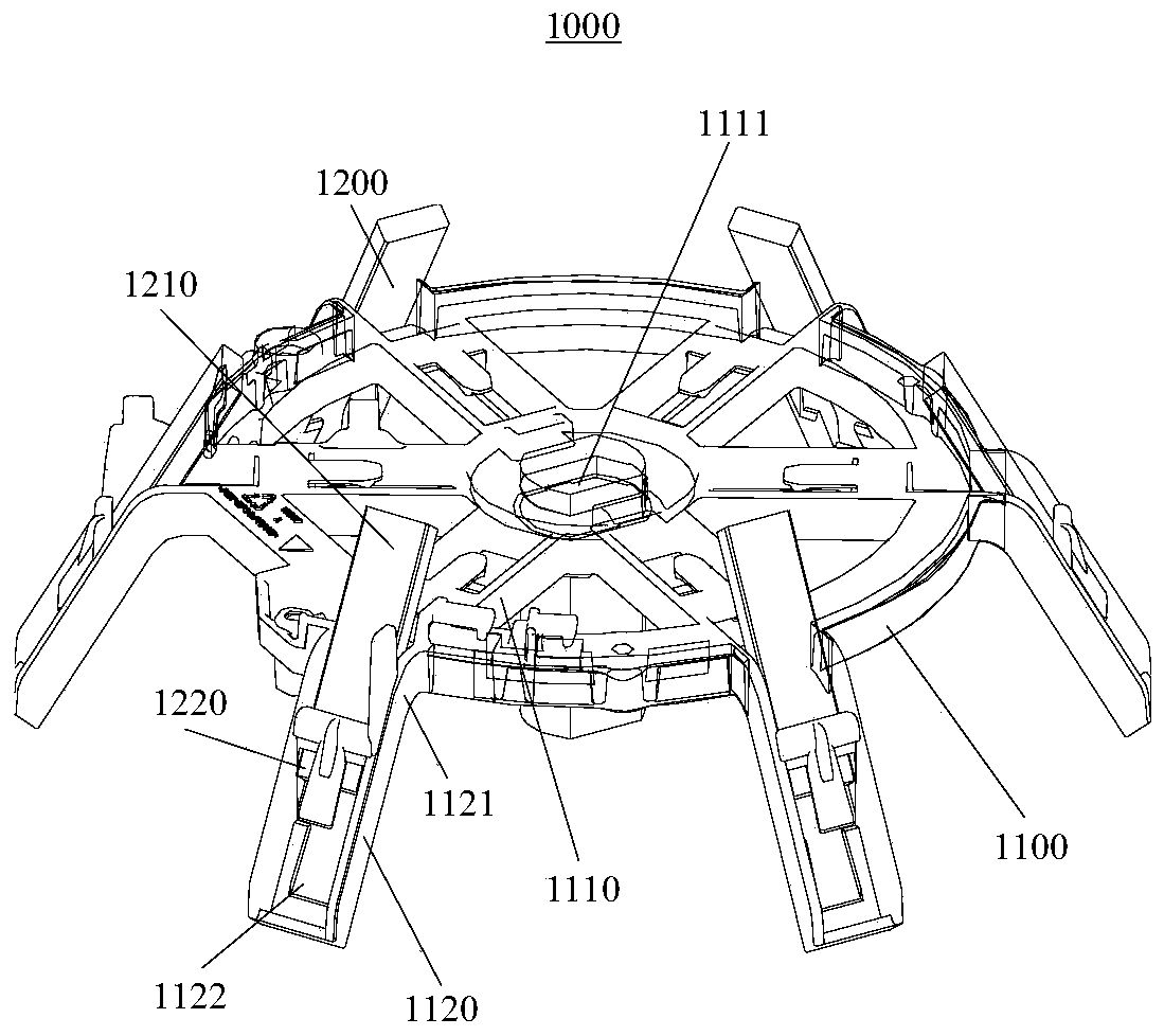
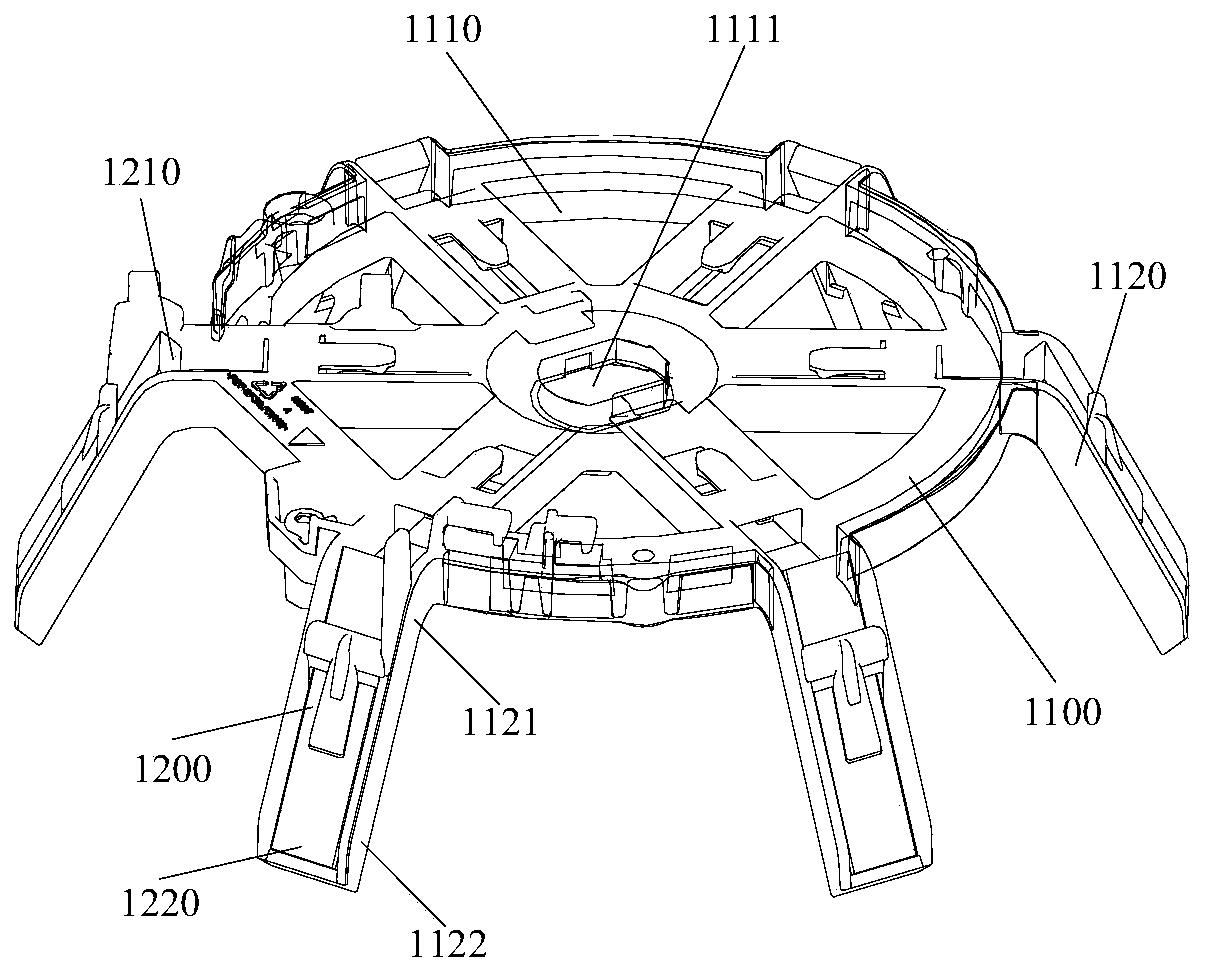
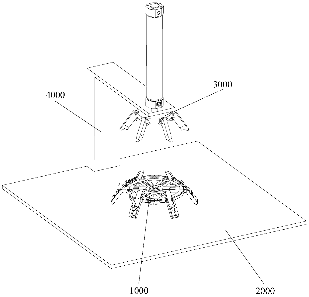
[0035] Such as image 3 and Figure 4As shown, this embodiment provides an assembly device for assembling the magnetic strip 1200 and the magnetic strip holder 1100, the assembly device includes: a base 2000 for carrying and fixing the magnetic strip holder 1100 and a plurality of magnetic strips 1200 The pre-installation part 1000; the installation part 3000, fixed above the base 2000, is used to press a plurality of magnetic strips 1200 from the pre-installation position to the working position, including a ramp assembly and a drive for pressing a plurality of magnetic strips 1200 The baroclinic component moves up and down the power component.
[0036] In the prior art, it is necessary to manually assemble the magnetic strip 1200 and the magnetic strip holder 1100 . During assembly, manpower is required to press-feed the magnetic strip 1200 at the pre-installation posi...
PUM
 Abstract
Description
Claims
Application Information