Bus connector and cabinet combination structure

A technology of busbar connectors and connecting parts, which is applied in connection, installation of busbars, cooling of busbar devices, etc., can solve problems such as inconvenient use, lack of early warning devices, cumbersome operation, etc., and achieve the effect of convenient use and quick troubleshooting

Active Publication Date: 2020-07-17
江苏大浪电气有限公司
View PDF7 Cites 8 Cited by
  • Summary
  • Abstract
  • Description
  • Claims
  • Application Information

AI Technical Summary

Problems solved by technology

[0003] However, there are still obvious defects in its use: 1. The connection between the busbar connector and the busbar needs to be waterproof and moisture-proof, otherwise there will be potential safety hazards such as electric shock and fire. The current conventional practice is to place a desiccant at the connection end , but the service life of the desiccant is limited. When the desiccant absorbs enough water and fails, the user often cannot detect and replace it in time, which is inconvenient to use. The above-mentioned device cannot effectively solve this problem, and the function is single; 2. The above-mentioned The busbar connector in the device is mostly used in the cabinet structure. After the cabinet is moved or the equipment is suddenly powered off, it is often necessary to manually open the connector to check whether there is a loose connection between the busbar and the connector. problem, and opening and reinstalling not only requires the use of tools, but also the operation is cumbersome, and the efficiency is also very low; 3. In the case of long-term use and improper operation, the inside of the busbar connector is very easy to accumulate heat and generate high temperature, which poses a safety hazard. The above-mentioned devices lack corresponding early warning devices, and cannot remind relevant personnel to pay attention in time

Method used


Image

  • Bus connector and cabinet combination structure
  • Bus connector and cabinet combination structure

Examples


Embodiment Construction

[0025] The following will clearly and completely describe the technical solutions in the embodiments of the present invention with reference to the accompanying drawings in the embodiments of the present invention. Obviously, the described embodiments are only some, not all, embodiments of the present invention. Based on the embodiments of the present invention, all other embodiments obtained by persons of ordinary skill in the art without making creative efforts belong to the protection scope of the present invention.

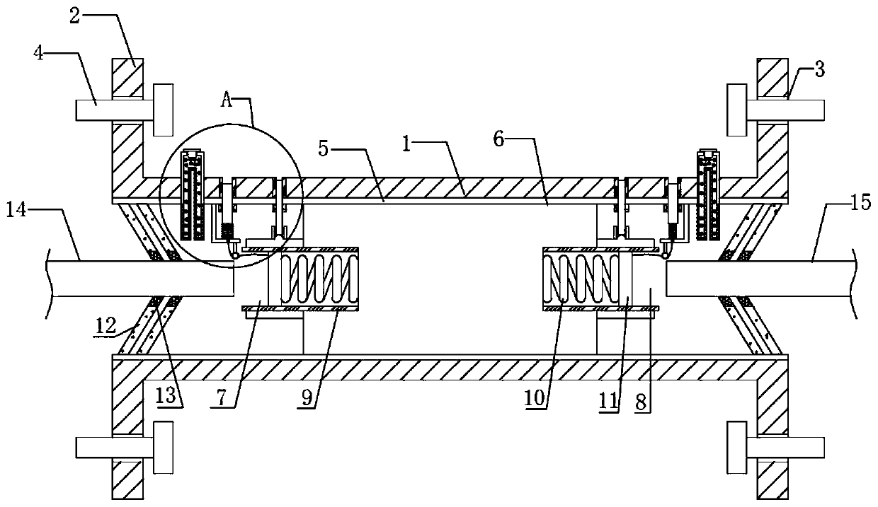
[0026] see Figure 1-2 , the present invention provides a technical solution:

[0027] A busbar connector, comprising an outer insulating sleeve 1, the two ends of the outer insulating sleeve 1 are symmetrically provided with connecting parts 2, the connecting part 2 is provided with a connecting threaded hole 3, and a connecting screw 4 is threaded in the connecting threaded hole 3 , the connection screw 4 can be used to fix the connecting part 2 of the busb...


PUM


Abstract

The present invention provides a bus connector and a cabinet combination structure. The bus connector comprises an outer insulating sleeve, an inner conductive block is fixedly arranged in an inner cavity of the outer insulating sleeve, and conductive springs are arranged in a first plugging port and a second plugging port. The ends, away from the inner conductive block, of the conductive springsare electrically connected with a conductive plate, a color-changing drying agent is placed in the drying cavity, and a reset spring is connected with a first indicating rod. A connecting rope penetrates through a rope penetrating hole formed in a supporting piece, bypasses a guide wheel and then is fixedly connected to the conductive plate, a thermal expansion part is arranged on the heat absorption layer, and a second indication rod penetrates through a through hole formed in the side wall of the outer insulation sleeve. The bus connector provided by the present invention can know whether the desiccant is invalid, whether the internal elements are overheated and whether a bus connecting end is loosened or not on the premise of not opening the connector, and has the advantages of centralized functions and convenience in use. The present invention also provides a cabinet combination structure of the bus connector, and the cabinet combination structure is very worthy of popularization.

Description

technical field [0001] The invention relates to the technical field of busbar connection, in particular to a busbar connector and a cabinet combining structure. Background technique [0002] In the prior art, the application number is "201720648301.4" for a busbar connector, a switch cabinet, a busbar connection structure and a combination cabinet. The busbar connector includes an insulating sleeve, a conductor, and two conductive fixtures. At both ends of the conductor, the conductive fixture includes a plurality of conductive sheets distributed around the circumference, a first elastic ring that surrounds the plurality of conductive sheets so that one end of the plurality of conductive sheets hugs the end of the conductor, and surrounds the plurality of conductive sheets to make the plurality of conductive sheets The other end can hold the second elastic ring of the external conductive part. The conductor and the two conductive clamps are arranged in the insulating sleeve....

Claims


Application Information

Patent Timeline
Patent Type & Authority Applications(China)
IPC IPC(8): H01R13/11H01R13/502H01R13/52H01R13/627H01R13/629H02B1/20H02G5/00H02G5/10
CPCH01R13/111H01R13/502H01R13/5227H01R13/627H01R13/629H02B1/20H02B1/202H02G5/00H02G5/10
Inventor 郑东升
Owner 江苏大浪电气有限公司
Why Eureka
Try Eureka