Hand model generation method, device, terminal equipment and hand motion capture method
A hand model and hand movement technology, applied in the field of motion capture, can solve problems such as inaccurate hand models
- Summary
- Abstract
- Description
- Claims
- Application Information
AI Technical Summary
Problems solved by technology
Method used
Image
Examples
Embodiment 1
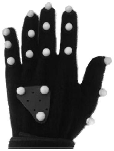
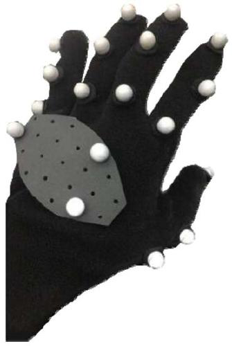
[0045] The inventors of the present application found in practice that when the existing glove layout is used for motion capture, if the user's hand is too small, the distance between the two reflective marker points is too close during the hand motion capture process, so that the algorithm cannot Identify the correct reflective markers. In order to ensure that the algorithm can correctly identify each reflective marking point during hand movement, the inventors of the present application proposed a new layout idea for the reflective marking points of motion capture gloves.
[0046] Aiming at the problem that the distance between the reflective marking points on the glove is too close for the user’s hand to be too small to accurately identify the marking points, when the motion capture glove of this application lays out the marking points, it aims at the marking points on the second, third, and fourth knuckles of the finger. When laying out, not all marker points are placed di...
Embodiment 2
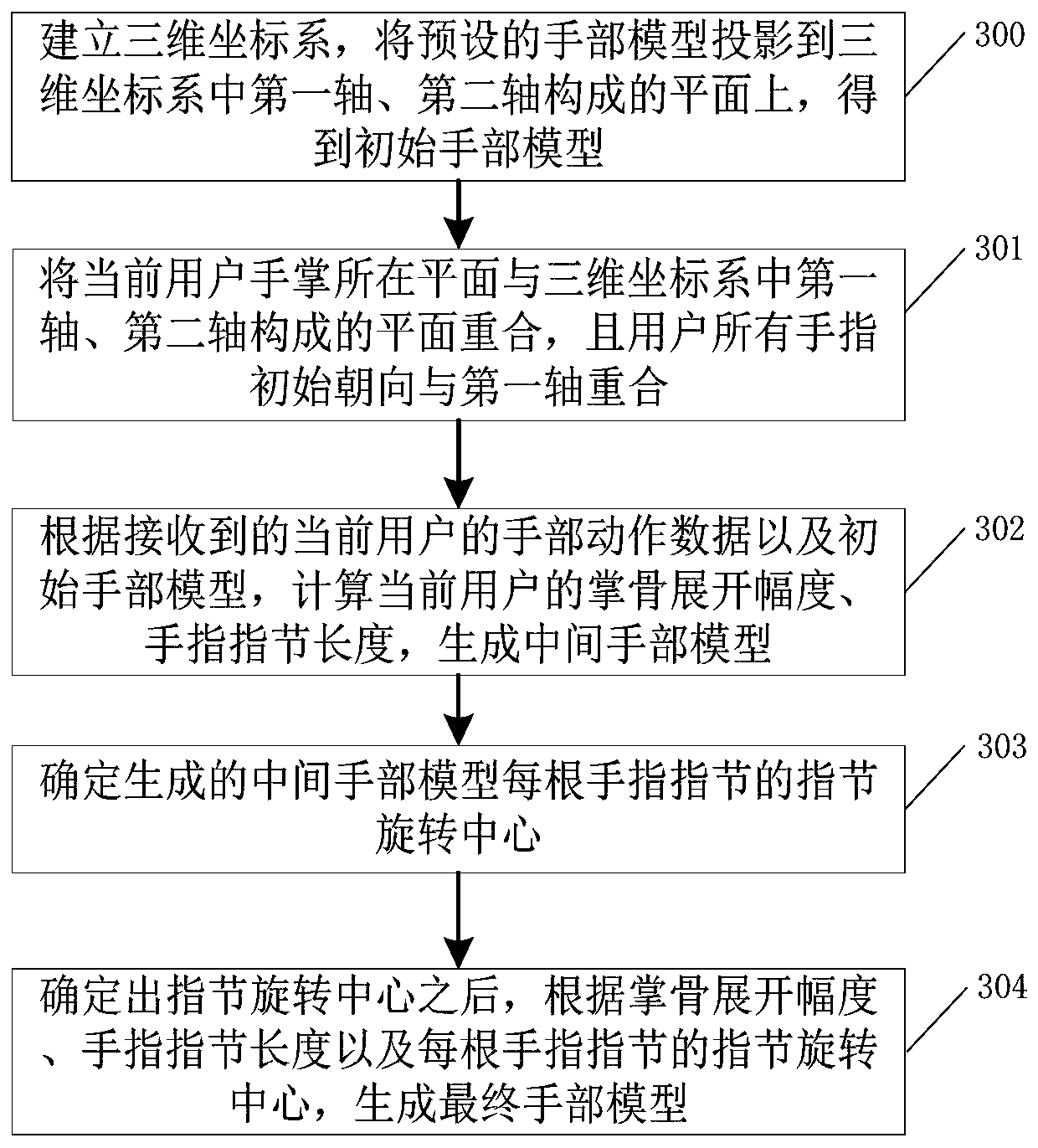
[0049] Such as image 3 As shown, it is a schematic flowchart of the first embodiment of a hand model generation method applied to hand motion capture provided by the present invention. The hand model generation method includes:
[0050] S300. Establish a three-dimensional coordinate system, and project the preset hand model onto a plane formed by the first axis and the second axis in the three-dimensional coordinate system to obtain an initial hand model.
[0051] A three-dimensional coordinate system is established, and the preset hand model (three-dimensional model) is projected onto the plane formed by the first axis and the second axis of the three-dimensional coordinate system to obtain an initial hand model. Wherein, the first axis and the second axis may be any two axes among x, y, and z axes. The corresponding initial hand model is a two-dimensional image without thickness. In all the embodiments below, the first axis is the x-axis, the second axis is the z-axis, a...
Embodiment 4
[0118] Such as Figure 7 As shown, it is a schematic flowchart of the third embodiment of a hand model generation method applied to hand motion capture provided by the present invention. The hand model generation method includes:
[0119] In step S700, a three-dimensional coordinate system is established, and the preset hand model is projected onto the plane formed by the first axis and the second axis in the three-dimensional coordinate system to obtain an initial hand model.
[0120] S701. The plane where the current user's palm is located coincides with the plane formed by the first axis and the second axis in the three-dimensional coordinate system, and the initial orientation of all fingers of the user coincides with the first axis, that is, the plane where the current user's palm is located coincides with the x-z plane and all fingers are oriented towards the x-axis.
[0121] S702. According to the received hand movement data of the current user, obtain the position in...
PUM
 Abstract
Description
Claims
Application Information
 - R&D
- Intellectual Property
- Life Sciences
- Materials
- Tech Scout
- Unparalleled Data Quality
- Higher Quality Content
- 60% Fewer Hallucinations
Browse by: Latest US Patents, China's latest patents, Technical Efficacy Thesaurus, Application Domain, Technology Topic, Popular Technical Reports.
© 2025 PatSnap. All rights reserved.Legal|Privacy policy|Modern Slavery Act Transparency Statement|Sitemap|About US| Contact US: help@patsnap.com


