
Soap box and method

A soap box and soap technology, applied in home appliances, sanitary equipment, applications, etc., can solve the problems of sticking residue, inconvenient soap taking, and affecting the cleanliness of the soap box, so as to reduce the contact area and ensure the cleanliness , to ensure the effect of stability

Active Publication Date: 2020-07-24
台州市黄岩神洛塑业有限公司
View PDF8 Cites 0 Cited by
  • Summary
  • Abstract
  • Description
  • Claims
  • Application Information

AI Technical Summary

Problems solved by technology

[0004] But existing soap box is in the process of using, because soap has just been used, makes the surface of soap be stained with a lot of moisture, and moisture can breed a lot of bacteria after long-time deposition in soap box, thereby put soap into After entering the soap box, the moisture will affect the cleanliness of the soap box and reduce the use effect of the soap
[0005] When the applicant invented this patent, after searching, it was found that the Chinese patent disclosed "a soap box", and its application number is "201610005817.7". This patent mainly discloses a problem of preventing the moisture on the soap from dripping quickly. However, when the water drips away from the position where the soap is placed, the water on the soap cannot completely drip or flow off, so that after a long period of prevention, the outer surface of the soap will soften due to the contact between the soap and the water , the moisture on the soap is dried naturally, and the softened part will be in close contact with the soap box, so that when the soap is taken out of the soap box, the soap seems to be stuck in the soap box, making the soap not very comfortable when taken. Convenient, at the same time, it is easy to get residual soap on the soap dish after taking the soap

Method used


Image

  • Soap box and method
  • Soap box and method
  • Soap box and method

Examples


Embodiment Construction

[0030] The following will clearly and completely describe the technical solutions in the embodiments of the present invention with reference to the accompanying drawings in the embodiments of the present invention. Obviously, the described embodiments are only some, not all, embodiments of the present invention. Based on the embodiments of the present invention, all other embodiments obtained by persons of ordinary skill in the art without making creative efforts belong to the protection scope of the present invention.

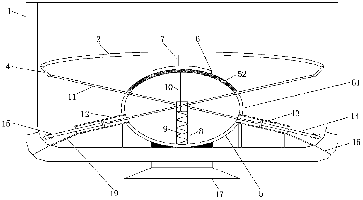
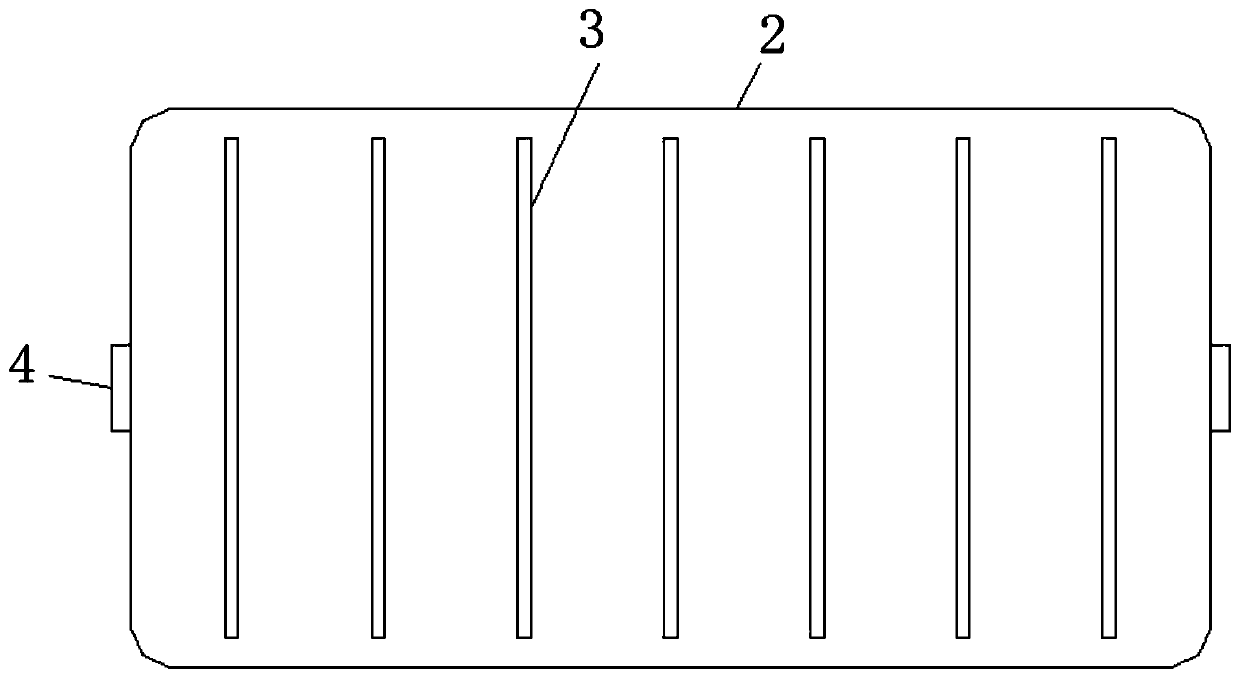
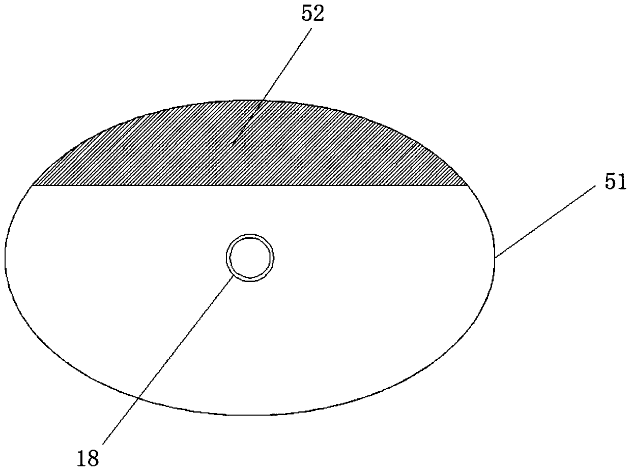
[0031] like Figure 1-3 As shown, the embodiment of the present invention provides a soap box, including a plastic box body 1, a suction cup 17 is installed in the middle of the bottom of the plastic box body 1, and the top of the plastic box body 1 is an opening, so that soap needs to pass through the soap box when taking it. The top of the plastic box body 1 is provided with a soft rubber plate 2. The material of the soft rubber plate 2 is silica gel. The s...


PUM


Abstract

The invention provides a soap box and a method, and relates to the field of living goods. A soft rubber plate is arranged in an inner cavity of a plastic box body, and a hollow cavity is formed in themiddle of the bottom of an inner cavity of the plastic box body. The top of a hard metal surface is connected with the bottom of the rubber material surface; the top of an extrusion rod is connectedwith the middle part of the bottom of the soft rubber plate; a compression spring is arranged in an inner cavity of a sleeve; the top of the compression spring is connected with a springback rod, thebottoms of the two sides of the surface of the hard metal communicate with fixing through pipes, the side, away from the long rod, of the piston is connected with a short rod, the end, away from the piston, of the long rod is connected with a pulling strip, and water outlets are formed in the bottoms of the two sides of the plastic box body. The pistons in the two fixed through pipes can slide outwards through extrusion of air, so that the long rod is driven to pull the soft rubber plate, the soft rubber plate is bent after being subjected to tension, the bent soft rubber plate is separated from the surface, making contact with soap, of the soft rubber plate, and the soap is convenient to take.

Description

[0001] This application is a divisional application with the application date of August 8, 2018 and the application number CN201810899240.8, whose invention name is a soap box. technical field [0002] The invention relates to the technical field of daily necessities, in particular to a soap box and a method. Background technique [0003] Soap is a common daily necessities in life. It has the effect of washing stains. There are many types of soap. Among them, in household life, soap generally needs to be placed in a soap box after use to facilitate the use of soap. [0004] But existing soap box is in the process of using, because soap has just been used, makes the surface of soap be stained with a lot of moisture, and moisture can breed a lot of bacteria after long-time deposition in soap box, thereby put soap into After entering the soap box, moisture will affect the cleanliness of the soap box and reduce the use effect of soap. [0005] When the applicant invented this p...

Claims


Application Information

Patent Timeline
Patent Type & Authority Applications(China)
IPC IPC(8): A47K5/03
CPCA47K5/03
Inventor 谈京金
Owner 台州市黄岩神洛塑业有限公司
Learn More