Horizontal rotary food fermentation equipment

A technology of food fermentation and equipment, which is applied in the field of horizontal rotary food fermentation equipment, can solve problems such as difficult to eliminate and excessive foam, and achieve the effect of avoiding difficult to handle

Inactive Publication Date: 2020-07-24
廖俊根
View PDF0 Cites 0 Cited by
  • Summary
  • Abstract
  • Description
  • Claims
  • Application Information

AI Technical Summary

Problems solved by technology

[0003] Aiming at the above-mentioned problems that too much foam is easily caused during the stirring process, and the more protein content in the wine, the greater the viscosity and concentration during fermentation, the foam generated is not only large but also difficult to eliminate, the invention provides a horizontal rotating food Fermentation equipment

Method used


Image

  • Horizontal rotary food fermentation equipment
  • Horizontal rotary food fermentation equipment
  • Horizontal rotary food fermentation equipment

Examples


Embodiment 1

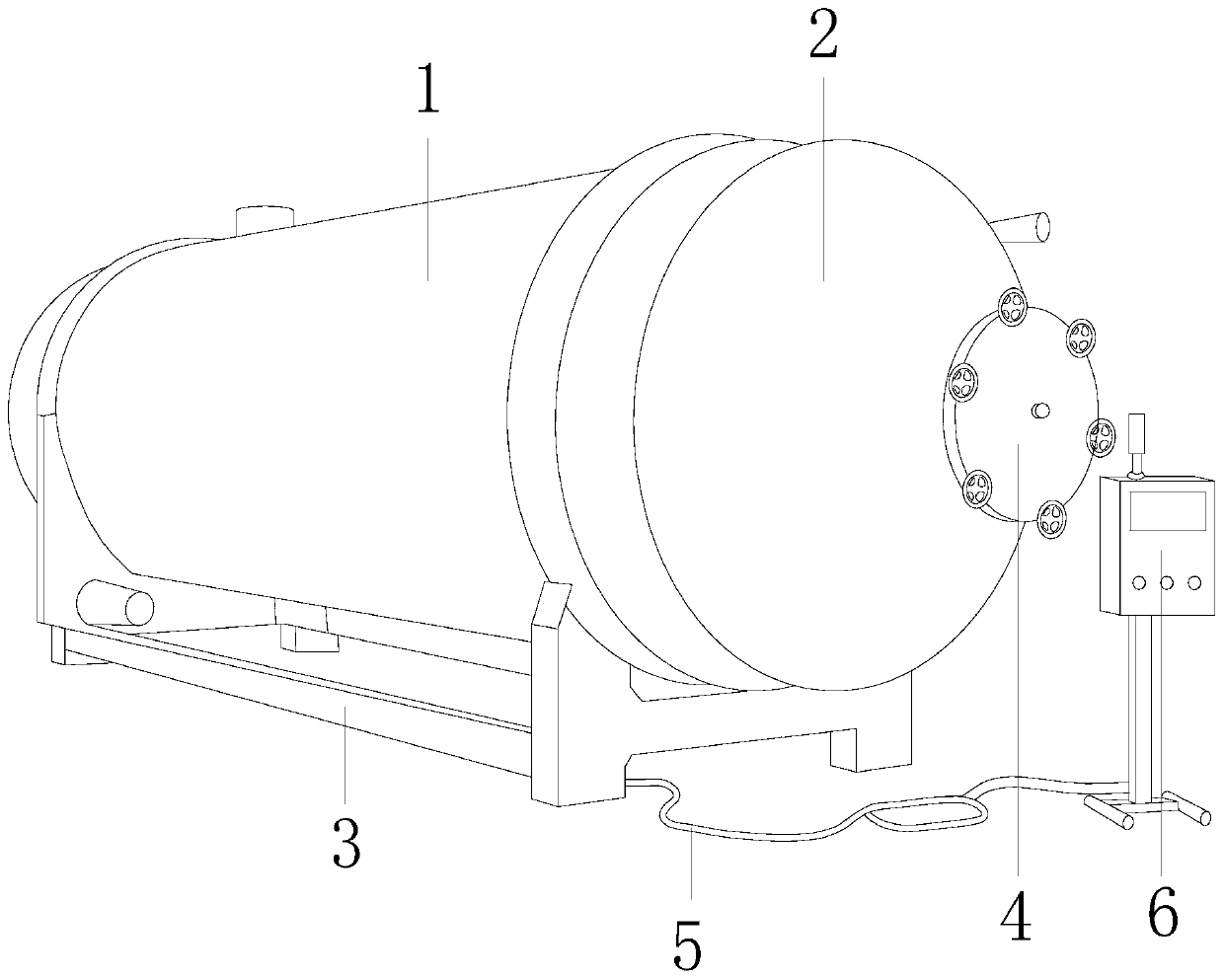
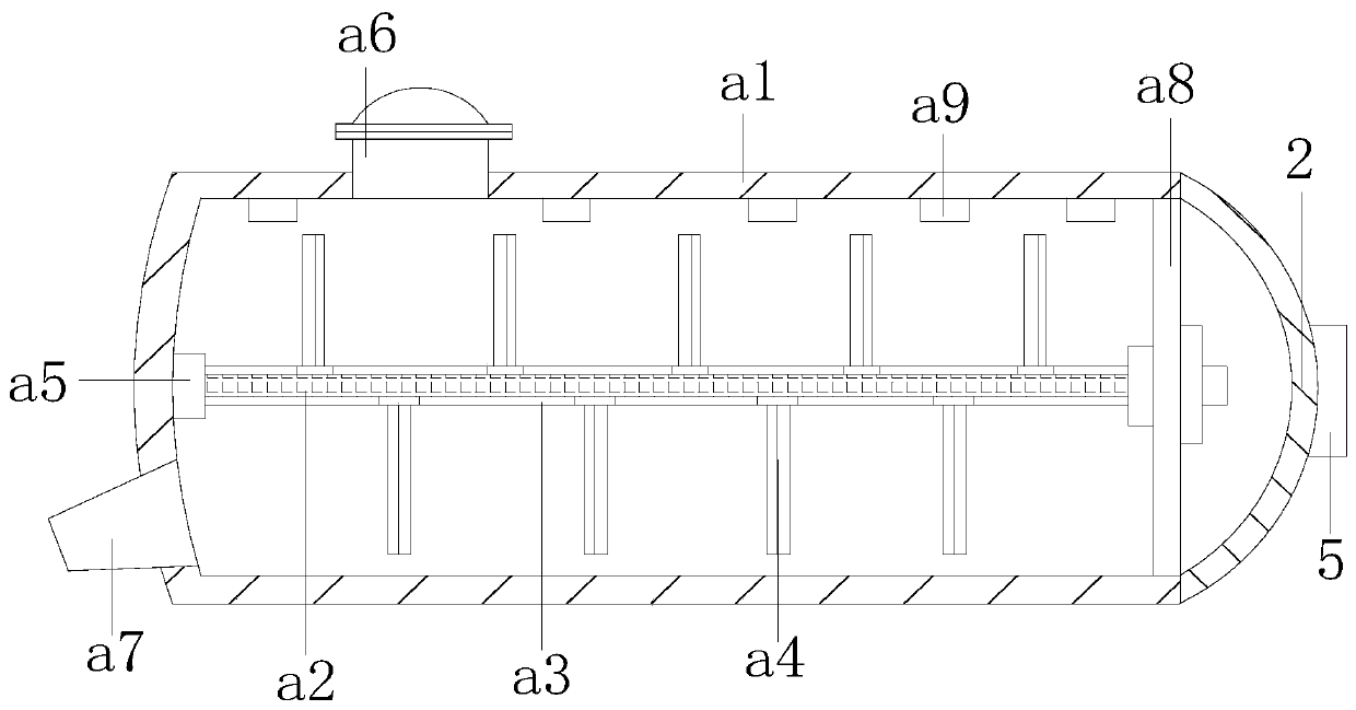
[0026] Such as Figure 1-Figure 5 Shown:

[0027] The present invention provides a horizontal rotary food fermentation equipment, the structure of which includes a fermentation tank 1, a tank cover 2, a bottom frame 3, a closed valve 4, a connecting line 5, and a console 6, and the tank cover 2 is hinged to the front end of the fermentation tank 1 , the closed valve 4 is threadedly connected to the front center of the tank cover 2, the console 6 is electrically connected to the fermenter 1 through the connection line 5, and the fermenter 1 is embedded and connected to the position directly above the bottom frame 3, and the The fermenter 1 mainly includes a tank body a1, a rotating shaft a2, a fixed sleeve a3, a defoamer paddle a4, a combination block a5, a feed door a6, a discharge port a7, an isolation plate a8, and a defoamer a9. a9 is embedded and fixedly connected to the top position of the inner wall of the tank body a1, the separation plate a8 is riveted and connected t...

Embodiment 2

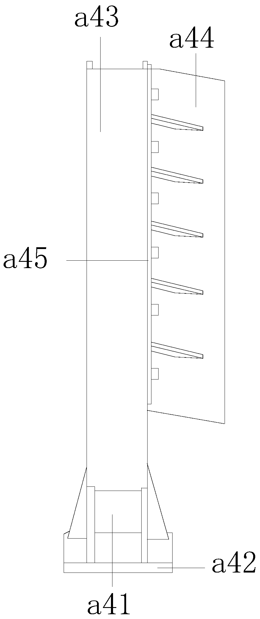
[0034] Such as Figure 6-Figure 8 Shown:

[0035] The present invention provides a horizontal rotating food fermentation equipment. The defoaming device a9 mainly includes a conduit c1, a hollow plate c2, an inclined block c3, a foam feed mechanism c4, and a foam feed channel c5. The conduit c1 passes through the hollow plate c2 In the middle position of the foam inlet channel c5, the foam inlet mechanism c4 is fixedly connected under the hollow plate c2, and the inclined block c3 is provided with two right-angled triangle structures, with the foam inlet mechanism c4 as the center line and symmetrically distributed left and right It can make it easier for the foam feeding mechanism c4 to engage between the inclined blocks c3.

[0036]Wherein, the foam feeding mechanism c4 mainly includes a blocking piece c41, a support ring c42, a chute c43, a support floating block c44, and a spacer c45. Fitted and installed inside the chute c43, the support floating block c44 is threadedly...


PUM


Abstract

The invention discloses horizontal rotary food fermentation equipment. The equipment structurally comprises a fermentation tank, a tank cover, a bottom frame, a sealing valve and a console; the fermentation tank is embedded and fixedly connected to a position right above the bottom frame; the fermentation tank comprises a tank body, a rotating shaft, a fixing sleeve, a defoaming paddle, a combining block, a feeding door, a discharging opening, an isolation plate and a defoaming device; the defoaming device is embedded and fixedly connected to the top end of the inner wall of the tank body; andthe defoaming paddle is in bolted connection with the periphery of the rotating shaft. The rotating shaft drives the defoaming paddle to rotate, and the auxiliary plate is in clearance fit in a movable groove. When a supporting plate drives the auxiliary plate to make contact with the grape wine liquid level, an inclined angle can be formed by the auxiliary plate, and the liquid surface is pushedto two sides, so that generation of foam is effectively reduced. When foam is generated, the foam can be in contact with the defoaming device, a supporting floating block pushes an isolation piece upwards in cooperation, and then the foam enters a foam inlet channel and is sucked away by a guide pipe, so that the problem that foam is difficult to treat is solved.

Description

technical field [0001] The invention relates to the field of food fermentation, and more specifically relates to a horizontal rotary food fermentation equipment. Background technique [0002] Food fermentation equipment is a kind of mechanical equipment that mixes food and yeast in an anaerobic state for transformation. Because wine is properly stirred during the fermentation process, it can not only press the grape skin into the wine, but also replenish Some oxygen can promote the proliferation of yeast and increase the production of wine, but it is easy to cause too much foam during the stirring process, and the more protein content in wine, the greater the viscosity and concentration during fermentation, and the foam produced is not only more but also difficult to eliminate. This will have a certain impact on the fermentation effect. Contents of the invention [0003] Aiming at the above-mentioned problems that too much foam is easily caused during the stirring process...

Claims


Application Information

Patent Timeline
Patent Type & Authority Applications(China)
IPC IPC(8): C12G1/024
CPCC12G1/0209
Inventor 廖俊根
Owner 廖俊根
Why Eureka
Try Eureka