Method for inserting a false twist into a thread and spinning machine and device for inserting a false twist into a thread

A spinning machine and yarn technology, applied in the field of devices implementing the method, can solve the problems that the spinning stability is not obviously improved, and achieve the effect of improving the spinning quality

Active Publication Date: 2020-07-24
MASCHINENFABRIK RIETER AG
View PDF10 Cites 0 Cited by
  • Summary
  • Abstract
  • Description
  • Claims
  • Application Information

AI Technical Summary

Problems solved by technology

However, spinning stability was not significantly improved when using different types of friction discs

Method used


Image

  • Method for inserting a false twist into a thread and spinning machine and device for inserting a false twist into a thread
  • Method for inserting a false twist into a thread and spinning machine and device for inserting a false twist into a thread
  • Method for inserting a false twist into a thread and spinning machine and device for inserting a false twist into a thread

Examples


Embodiment Construction

[0040] In the following description of the alternative exemplary embodiment, the same reference numerals are used for features that are identical and / or at least similar in terms of their design and / or mode of operation compared to the other exemplary embodiments. As long as these features are not explained again in detail, their configuration and / or mode of operation correspond to those of the features already described above. The mentioned rollers can have different outer sides, which are in particular cylindrical, conical or parabolic, even though only cylinders are mentioned in individual cases.

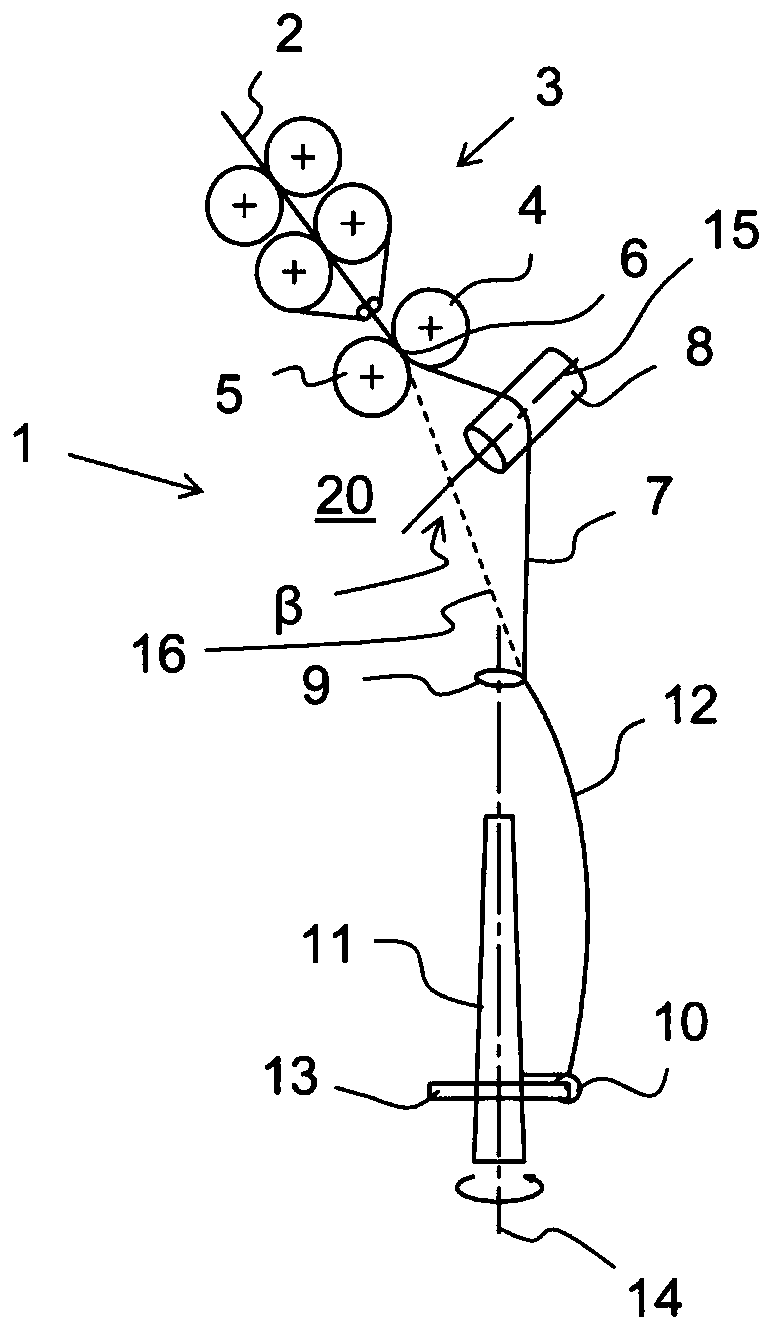
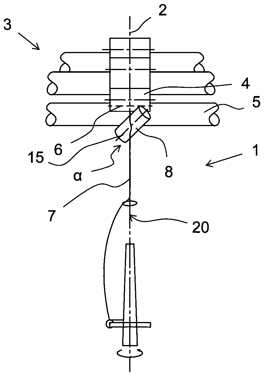
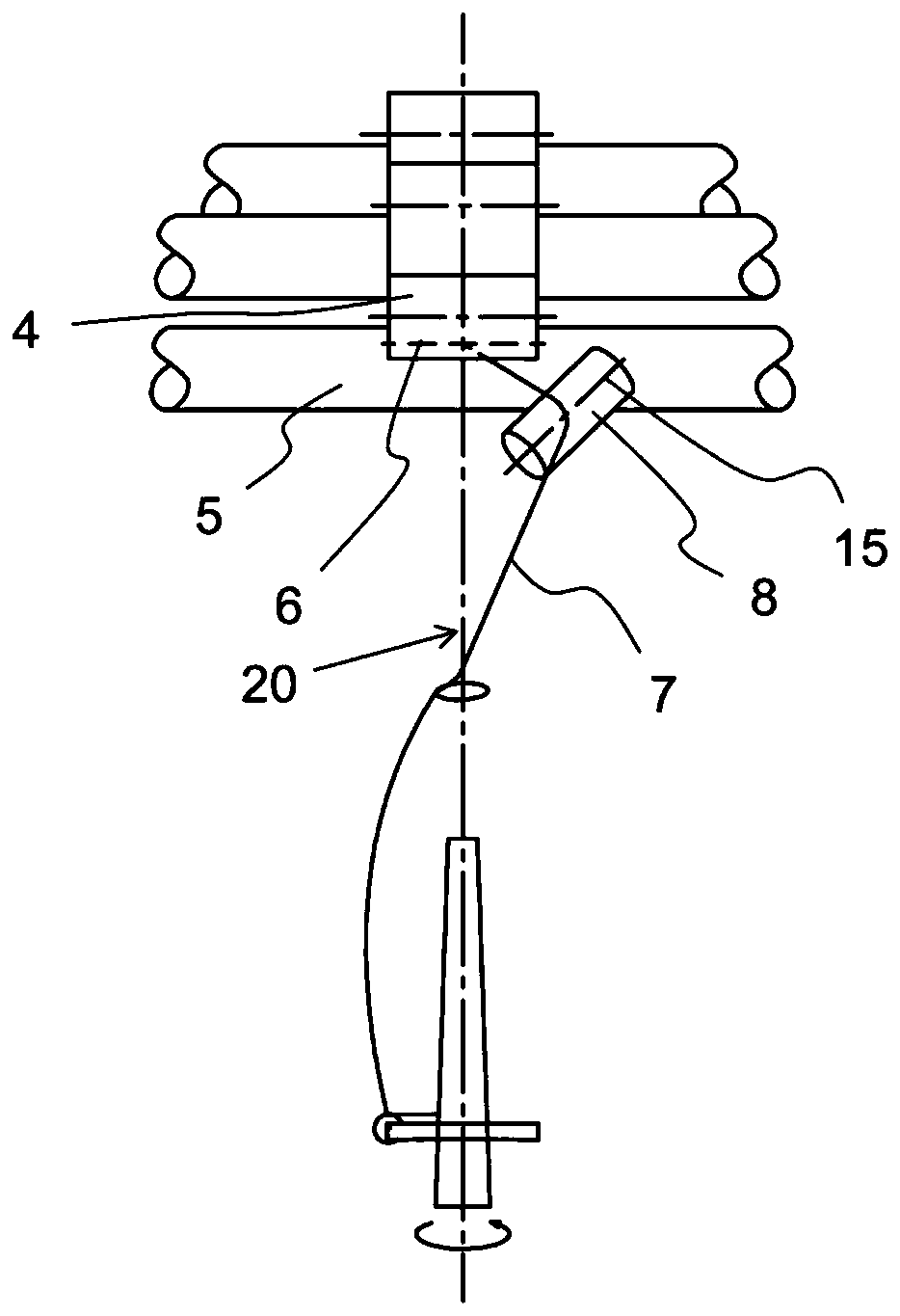
[0041] figure 1 A side view of the spinning position 1 of the ring spinning machine is shown. The fiber strand 2 passes through a drafting device 3 and is drawn there. The fiber strands leave the drafting device 3 at a roller pair formed by an upper roller 4 and a lower roller 5 . The upper roller 4 and the lower roller 5 form an output clamping station 6 in which the fiber st...


PUM

PropertyMeasurementUnit
lengthaaaaaaaaaa
lengthaaaaaaaaaa

Abstract

The invention relates to a method and a spinning machine for inserting a false twist into a thread (7), wherein a thread running plane (20) is formed by the course of the thread (7) directly through adrafting device (3) to a large extent in plan view up to the spinning machine and the thread (7) exits the drafting device (3) at an output clamping point (6) formed by an upper roller (4) and/or a lower roller (5). The thread (7) is operated between the output clamping position (6) and the spinning position by means of a roller (8) which rotates about an axis of rotation (15) that is oblique tothe thread running plane (20). The thread (7) is rotated about its longitudinal axis at the same time and a first false twist is inserted into the thread (7). The thread (7) is moved laterally out ofthe thread running plane (20) by means of the roller (8), and the thread (7) is brought into contact with the upper roller (4) and/or the lower roller (5) after the output clamping position (6) in such a way that the upper roller (4) and/or the lower roller (5) inserts a second false twist into the thread (7). The device for inserting a false twist into a thread (7) on a spinning machine comprisesa device support (21) for fastening a roller to the structure of the spinning machine.

Description

technical field [0001] The invention relates to a method for introducing false twist into a yarn, wherein the yarn is formed by its course, which in plan view is largely direct, through the drafting device to the spinning unit running plane and the yarn leaves the drafting device at an output clamping position consisting of upper and / or lower rolls, wherein the yarn passes between the output clamping position and the spinning position through the The drum runs with its axis of rotation obliquely to the yarn run plane, while the yarn simultaneously rotates about its longitudinal axis and a first false twist is added to the yarn. And the invention relates to a spinning machine and a device for carrying out the method. Background technique [0002] Known false twist mechanisms for adding false twist to a yarn are based on the aspect of using a rotating false twist element to deflect the yarn from the position where it was originally drawn. Twist is imparted to the yarn, which...

Claims


Application Information

Patent Timeline
Patent Type & Authority Applications(China)
IPC IPC(8): D01H7/92
CPCD01H7/923
Inventor G·斯塔莱克
Owner MASCHINENFABRIK RIETER AG
Why Eureka
Try Eureka