Quick-change shell pulling hook shaft limiting protection structure

A technology of limit protection and shell hook, which is applied in the field of firearms, can solve the problems of large structural size of the machine head, escape of the shell hook shaft, and large opening and closing resistance, so as to improve mobility, good maintainability, and easy replacement and the effect of disassembly and cleaning

Pending Publication Date: 2020-07-24
CHONGQING JIANSHE IND GRP
View PDF0 Cites 0 Cited by
  • Summary
  • Abstract
  • Description
  • Claims
  • Application Information

AI Technical Summary

Problems solved by technology

[0002] Foreign AR series rifles such as M16, M4, etc., all use cylindrical shell hook shafts. During the unlocking/locking working cycle, the shell hook shafts are completely blocked by the machine frame to prevent them from escaping. The advantages are: The structure is simple and the workmanship is good, but its structure is only suitable for structures with small unlocking/locking strokes. A small opening and closing stroke means a large opening and closing helix angle and a small free travel after locking, and a large opening and closing helix angle brings opening and closing resistance The big problem is that the free stroke after locking is small, only the elastic shell ejection structure can be used, and the ejection spring of the e

Method used


Image

  • Quick-change shell pulling hook shaft limiting protection structure
  • Quick-change shell pulling hook shaft limiting protection structure
  • Quick-change shell pulling hook shaft limiting protection structure

Examples


Embodiment Construction

[0028] The working principle and structure of the present invention will be further described in detail below in conjunction with the embodiments and the accompanying drawings.

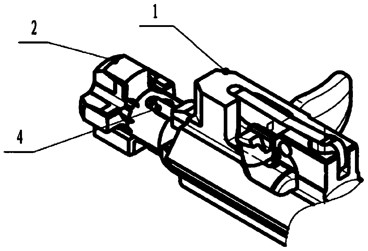
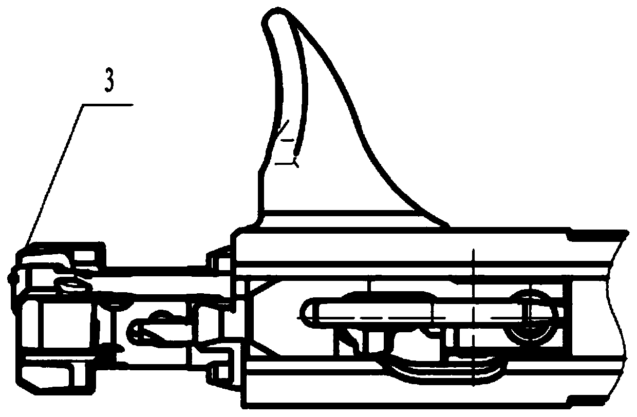
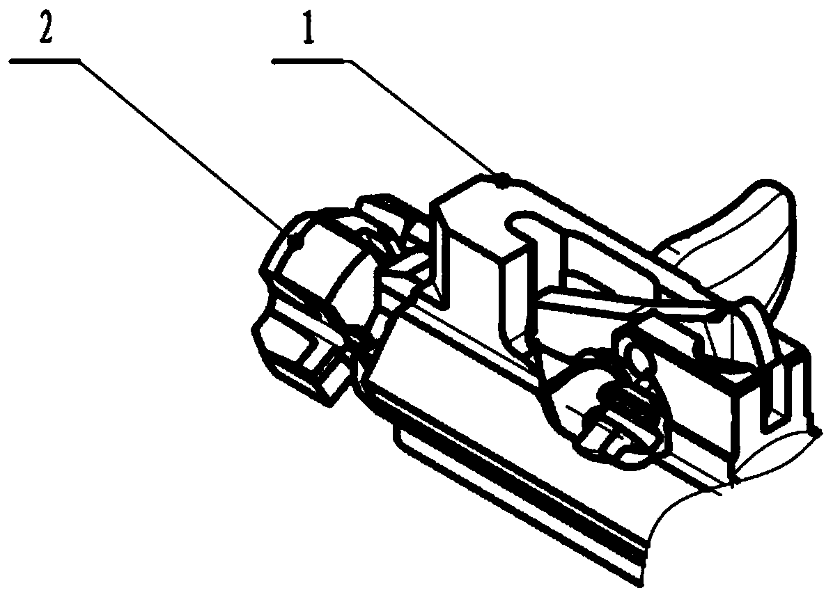
[0029] like Figure 1 to Figure 8 As shown, it is a quick-change shell hook shaft limit protection structure for a certain type of firearm, including a machine frame body 1, a machine head body 2 socketed in the machine frame body 1, and a puller connected to the machine head body 2. The shell hook 3 in the shell hook groove and the shell hook shaft 4 installed on the machine head body 2, the front end of the machine frame body 1 is provided with a protruding shoot 101 in the axial direction, and the protruding shoot 101 is unlocked when the bolt is unlocked. In the state, it is located directly behind the locking teeth of the machine head body, and is used to compress the shell hook shaft 4. The shell hook shaft 4 includes a rod portion 404 and a head portion 401. The front end of the rod portion of ...


PUM


Abstract

The invention discloses a quick-change shell pulling hook shaft limiting protection structure. The quick-change shell pulling hook shaft limiting protection structure comprises a machine frame body, amachine head body, a shell pulling hook and a shell pulling hook shaft installed on the machine head body; a convex bamboo shoot is arranged at the front end of the machine frame body in the axial direction, and the convex bamboo shoot is located right behind a locking tooth of the machine head body in the unlocking state of a bolt and used for pressing the shell pulling hook shaft; the shell pulling hook shaft comprises a rod part and a head part, a containing groove is formed in the front end of the rod portion of the machine head body in the axial direction and used for containing the headportion of the shell pulling hook shaft and preventing the head portion of the shell pulling hook shaft from twisting, and a through hole is formed in the containing groove in the radial direction and used for installing the rod portion of the shell pulling hook shaft; and in the unlocking/locking work cycle of the bolt, the head of the shell pulling hook shaft is always blocked by the bottom ofthe convex bamboo shoot at the front end of the machine frame body and does not jump out of the machine head body. By means of the structure, the maintenance performance of the bolt can be improved, the rapid replacement, disassembly and cleaning requirements of the shell pulling hook shaft are met conveniently, the peripheral size of a machine head is not occupied, the size of a firearm locking part is not increased, firearm weight reduction is facilitated, and maneuverability is improved.

Description

technical field [0001] The invention relates to the technical field of firearms, in particular to a quick-change shell-pull hook shaft limit protection structure. Background technique [0002] Foreign AR series rifles such as M16, M4, etc., all use cylindrical shell hook shafts. During the unlocking / locking working cycle, the shell hook shafts are completely blocked by the machine frame to prevent them from escaping. The advantages are: The structure is simple and the workmanship is good, but its structure is only suitable for structures with small unlocking / locking strokes. A small opening and closing stroke means a large opening and closing helix angle and a small free travel after locking, and a large opening and closing helix angle brings opening and closing resistance The big problem is that the free stroke after locking is small, only the elastic shell ejection structure can be used, and the ejection spring of the elastic shell ejection structure can be used to overcom...

Claims


Application Information

Patent Timeline
IPC IPC(8): F41C7/00F41A3/00F41A35/00
CPCF41A3/00F41A35/00F41C7/00
Inventor 黄光富朱开钰黄俊刘科言蔡崧罗波雷枫桥王冲叶云凯宋维东张渝龙建华李小平幸宁波庞方跃郑宏
Owner CHONGQING JIANSHE IND GRP
Why Eureka
Try Eureka