Automatic injection device

A technology of automatic injection and injection components, which is applied in the field of medical appliances, can solve problems such as rupture, high failure rate, and many parts involved, and achieve the effects of improving reliability and safety, ensuring medical effects, and simple structure

Pending Publication Date: 2020-07-28
宁波睿爱产品设计有限公司
View PDF1 Cites 9 Cited by
  • Summary
  • Abstract
  • Description
  • Claims
  • Application Information

AI Technical Summary

Problems solved by technology

[0005] This device can only be used for training. If it is used as a real syringe, there will be many problems: 1. The first sounding part is connected to the piston rod. If the sound can be heard, the first sounding part needs to be fast enough. impact on the bottom wall of the bar-shaped groove, because the injection simulation component as a whole moves synchronously with the first sounding part in the initial state, the injection simulation component will also quickly move downward and hit the piston in the needle tube, and the moving speed is too fast It will cause the needle tube (not shown in the figure, the tube body of the injection simulation assembly can be movably inserted in the needle tube) to break; if in order to prevent the needle tube from breaking, the running speed of the injection simulation assembly cannot be too fast, but the impact of the first sounding part on the It is very likely that there will be no sound on the strip groove. In short, the sound of the above-mentioned patent is related to the running speed of the injection simulation component. It is difficult to ensure the sound without damaging the needle tube; 2. In order to prevent the needle from being exposed, it is necessary to set More parts to prevent the movable sleeve from moving up, resulting in more involved parts and high failure rate

Method used


Image

  • Automatic injection device
  • Automatic injection device
  • Automatic injection device

Examples


Embodiment Construction

[0048] The present invention will be further described in detail below in conjunction with the accompanying drawings and embodiments.

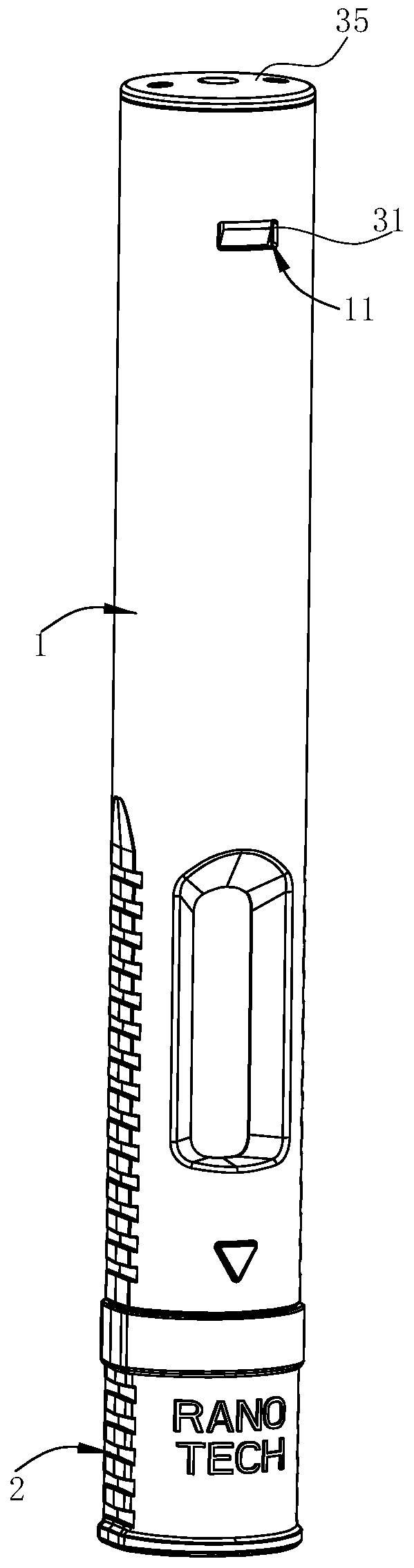
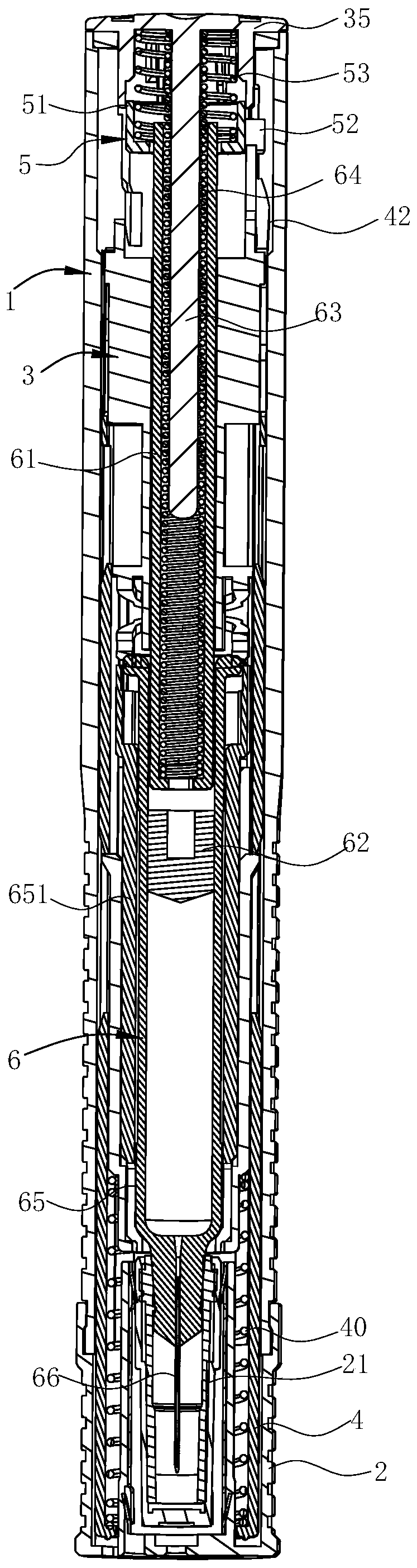
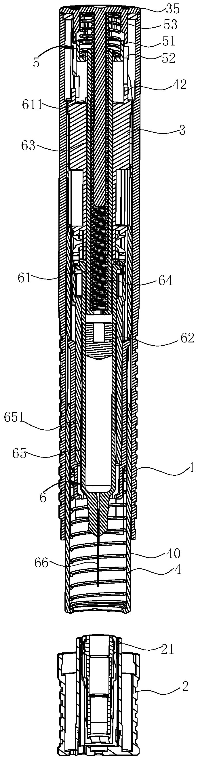
[0049] Such as Figure 1-22 As shown, the automatic injection device of this preferred embodiment includes a tube body 1, a cap body 2, a fixed sleeve 3, a movable sleeve 4, a sounding part 5 and an injection assembly 6, the lower end of the tube body 1 is open, and the cap body 2 is covered on the The lower end of the tube body 1 is in the shape of a pen holder, which is small in size and easy to use.

[0050] Such as figure 2 , 3 , 4, the movable sleeve 4 is arranged in the tubular body 1, and the lower end of the movable sleeve 4 can extend out of the tubular body 1 and move upward relative to the tubular body 1 when pressed by the skin. The downward trend is always maintained.

[0051] The movable sleeve 4 is set on the fixed sleeve 3, and the fixed sleeve 3 is positioned relative to the pipe body 1. The side wall of the movable sleev...


PUM


Abstract

The invention relates to an automatic injection device. The automatic injection device comprises a pipe body, a fixed sleeve, an injection assembly, a sound production element, a movable sleeve, a first elastic element and a second elastic element, wherein the sound production element comprises an annular body and sound production blocks; the annular body is coaxially and movably arranged in the fixed sleeve; the sound production blocks are arranged on a peripheral wall of the annular body; the sound production blocks penetrate out of the fixed sleeve in a radial direction and the sound production blocks and the fixed sleeve are relatively positioned through corresponding positioning structures; sliding grooves for the sound production blocks to axially move downwards after freeing from the corresponding positioning structures are formed in the fixed sleeve; each sound production block can produce a sound when bumping against an inner wall of one sliding groove; the movable sleeve sleeves the fixed sleeve; the lower end of the movable sleeve can extend out of the pipe body; the movable sleeve is provided push parts capable of pushing the sound production blocks to move to free fromthe corresponding positioning structures when moving upwards; the first elastic element acts on the sound production element, so that the sound production element keeps moving downwards all the time;and the second elastic element acts on the movable sleeve, so that the movable sleeve keeps moving downwards all the time. The sound production element prompts a user to start the injection, so thatthe safety is high.

Description

technical field [0001] The invention belongs to the technical field of medical appliances, and in particular relates to an automatic injection device. Background technique [0002] The most common way of administering the drug is by injection, eg intravenously, subcutaneously or intramuscularly, a syringe containing the drug is used for the injection, which is usually administered by trained healthcare personnel. In some cases, where regular injections of medication are required, it may be desirable for a patient or other individual to use a syringe to self-inject or give injections to other individuals, and devices for automatic injections have been developed to allow patients to self-inject. [0003] However, since patients are usually neither nurses nor educated in medical devices, such devices for automatic injection must prove to be simple and safe to use. Therefore, it is important for the user to be informed that the product has been injected, has been substantially ...

Claims


Application Information

Patent Timeline
Patent Type & Authority Applications(China)
IPC IPC(8): A61M5/20
CPCA61M5/20A61M2005/2006A61M2205/18
Inventor 侯士双袁霞林陈常娇胡高扬
Owner 宁波睿爱产品设计有限公司
Why Eureka
Try Eureka