A kind of staggered installation method of the lower furnace shell of a hot blast furnace and the equipment in the furnace

An installation method and hot blast furnace technology, which is applied to blast furnace parts, metal processing equipment, furnaces, etc., can solve the problems of long construction period and shortened construction period, and achieve the effects of shortening construction period, ensuring installation accuracy, and ensuring accuracy

Active Publication Date: 2022-03-08
CHINA MCC17 GRP
View PDF0 Cites 0 Cited by
  • Summary
  • Abstract
  • Description
  • Claims
  • Application Information

AI Technical Summary

Problems solved by technology

[0004] The purpose of the present invention is to overcome the problem that the overall construction period of the lower part of the hot blast stove is longer in the prior art, and to provide a method for interlaced installation of the lower furnace shell of the hot blast stove and the equipment in the furnace; the present invention will hoist the first belt furnace shell to the furnace shell After the bottom plate, release the vertical and horizontal centerlines and mark them, so as to facilitate the installation of I-beams, support columns and other components inside the furnace shell, and finally hoist the second furnace shell, and install the first The bottom plates are welded to realize the installation of the lower part of the hot blast stove. The whole installation operation process realizes the staggered installation of the furnace shell and the equipment, and effectively shortens the construction period under the premise of ensuring the installation accuracy of the equipment.

Method used


Image

  • A kind of staggered installation method of the lower furnace shell of a hot blast furnace and the equipment in the furnace
  • A kind of staggered installation method of the lower furnace shell of a hot blast furnace and the equipment in the furnace
  • A kind of staggered installation method of the lower furnace shell of a hot blast furnace and the equipment in the furnace

Examples


Embodiment

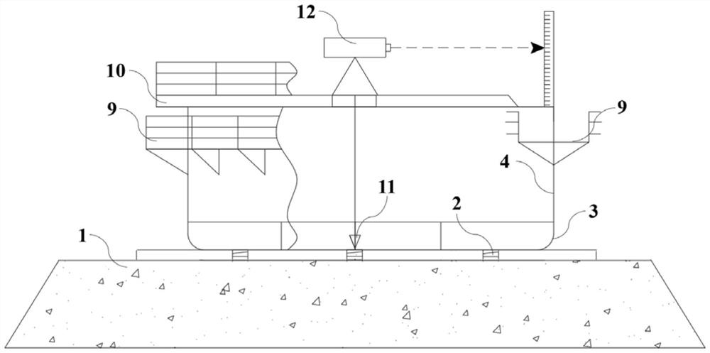
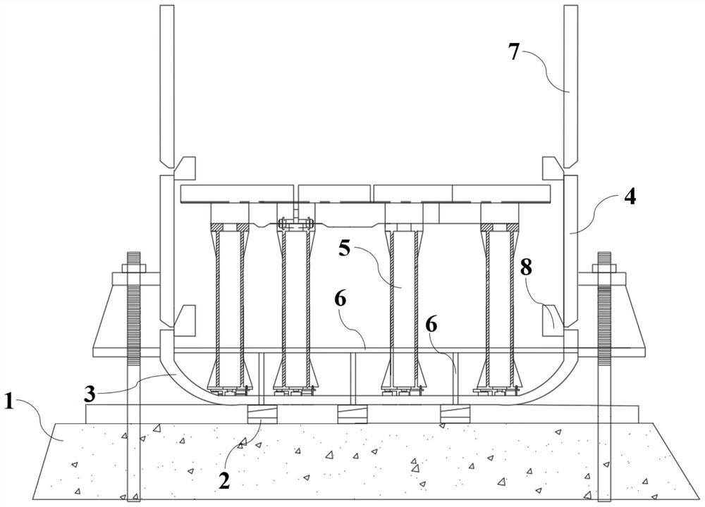
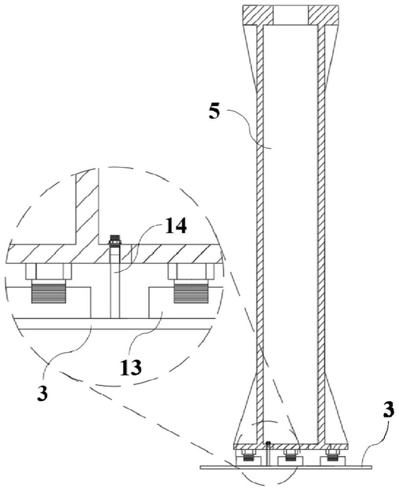
[0036] In the prior art, during the installation process of the lower part of the hot blast stove as a whole, in order to ensure the accuracy of the installation of various equipment inside the furnace shell, after the furnace shell of the hot blast stove is fixed and installed in advance, the various devices inside the furnace shell are installed. After the installation of the furnace shell is completed, the furnace shell is a whole, and its position will not change. Therefore, it is convenient for the operator to find the installation reference point when installing each device, so as to ensure the accuracy of the installation. However, due to the installation of the furnace shell After completion, the construction work area is limited and difficult to operate, resulting in a longer construction period.

[0037] In order to solve the above problems, a method for staggered installation of the lower furnace shell of the hot blast stove and the equipment in the furnace according...


PUM


Abstract

The invention discloses a method for interlaced installation of the lower furnace shell of a hot blast stove and equipment in the furnace, and belongs to the technical field of hot blast stove equipment installation. The process of the present invention is as follows: step a, install the bottom plate of the furnace shell on the base; step b, hoist the first belt furnace shell, and place the first belt furnace shell on the bottom plate of the furnace shell; step c, install the bottom plate of the furnace shell Put out the vertical and horizontal center line of the furnace grate, and mark the first belt furnace shell and the bottom plate of the furnace shell; step d, install the I-beam at the bottom of the furnace and the support column according to the mark; step e, install on the support column Furnace grate, at the same time carry out the hoisting of the second belt furnace shell and put it in place, and weld between the first belt furnace shell and the bottom plate of the furnace shell. The entire installation operation process realizes the staggered installation of the furnace shell and the equipment, and effectively shortens the construction period on the premise of ensuring the installation accuracy of the equipment.

Description

technical field [0001] The invention relates to the technical field of installation of hot blast stove equipment, and more specifically, relates to a method for interlaced installation of the lower furnace shell of the hot blast stove and the equipment in the furnace. Background technique [0002] As the main equipment of the smelter, the hot blast stove is an equipment that integrates combustion and heat transfer, and occupies a pivotal position in the smelter. In the process of installation and construction of the lower part of the hot blast stove in the current technology, after the furnace shell of the hot blast stove is installed in advance, the internal equipment of the hot blast stove is installed in sequence, although this installation process can ensure that the subsequent installation of corresponding equipment inside the furnace shell Accuracy, but the whole construction period is relatively long, and the installation efficiency is low, so further improvement is n...

Claims


Application Information

Patent Timeline
Patent Type & Authority Patents(China)
IPC IPC(8): B23P21/00C21B9/00
CPCB23P21/004C21B9/00
Inventor 房政丁汉俊郑治飞
Owner CHINA MCC17 GRP
Why Eureka
Try Eureka