

Indoor inspection and fire fighting integrated robot
A robot and fire-fighting technology, applied in the field of intelligent robots, can solve problems such as difficult implementation and low inspection efficiency, and achieve the effects of avoiding wear, ensuring safety, and facilitating maintenance
- Summary
- Abstract
- Description
- Claims
- Application Information
AI Technical Summary
Problems solved by technology
Method used
Image

Examples
Embodiment 1
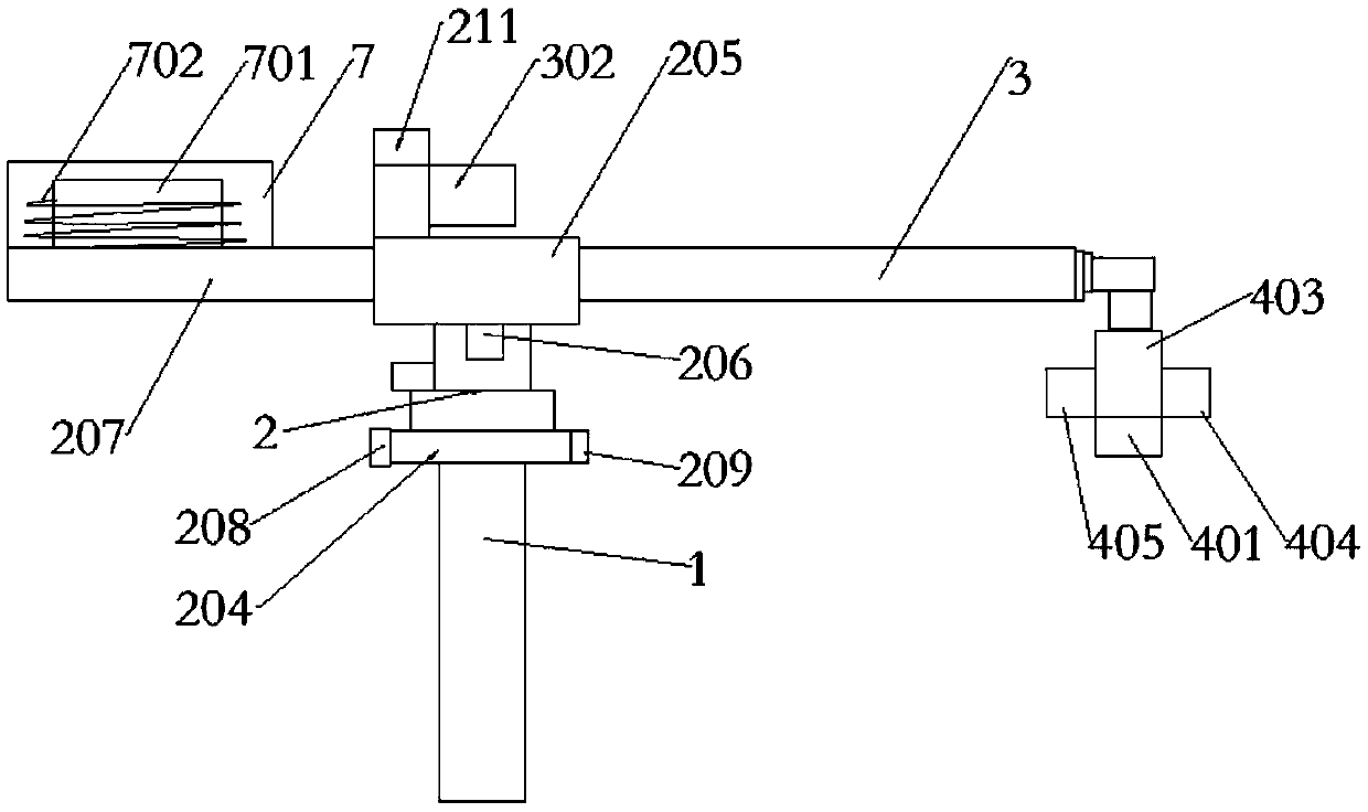
[0066] Indoor inspection robots, such as figure 1 As shown, it includes a column 1, an electric rotary table 2, an electric telescopic push rod 3 and an actuator 4. The electric rotary table 2 is installed on the column 1, and the electric telescopic push rod 3 is installed on the electric rotary table 2. The electric rotary table 2 drives The electric telescopic push rod 3 rotates, and the actuator 4 is located at the end of the electric telescopic push rod 3 . The electric turntable 2 can rotate 360° around the center of the column 1 in the horizontal plane, thereby driving the electric telescopic push rod 3 to rotate 360° in the horizontal plane, so as to realize all-round inspection of indoor equipment without dead ends.
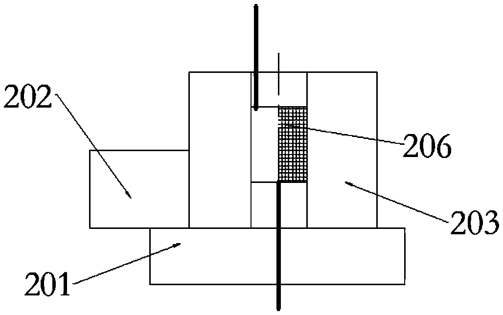
[0067] As a specific example, such as figure 2 As shown, the electric turntable 2 includes a base 201 , a motor 202 and a turntable 203 , the base 201 is fixed to the column 1 , the motor 202 is fixed to the base 201 , and the output shaft of the motor...
Embodiment 2
[0077] The difference between Embodiment 2 and Embodiment 1 is that the electric rotary table 2 of Embodiment 2 is provided with an electric lifting push rod 8 , and the actuator is arranged at the end of the electric lifting push rod 8 . The electric turntable 2 can rotate 360° around the center of the column 1 in the horizontal plane, and the electric turntable 2 drives the electric lifting push rod 8 to rotate, so as to realize multi-directional inspection of indoor equipment.
[0078] As a specific example, such as Figure 8 with 9 As shown, an electric telescopic push rod 3 is arranged between the electric rotary disk 2 and the electric lift push rod 8 , the electric lift push rod 8 is fixed on the end of the electric telescopic push rod 3 , and the actuator 4 is fixed on the electric lift push rod 8 . The electric turntable 2 can rotate 360° around the center of the column 1 in the horizontal plane, the electric telescopic push rod 3 can stretch in the horizontal direct...
Embodiment 3
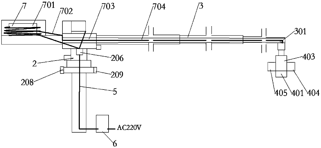
[0088]The electric rotary table 2 , the electric telescopic push rod 3 and the electric lift push rod 8 all need a control cable and a power cable 5 to transmit power and control signals. If the control cable and the power cable 5 are arranged outside the mechanism, they are easy to be entangled with each other and are easy to wear.
[0089] Described robot is provided with control cable and power cable 5, and the arrangement mode of control cable and power cable 5 has two kinds:
[0090] The first option:
[0091] Such as image 3 with 8 As shown, the column 1 is provided with a control box 6, and the inside of the turntable 203 is provided with a slip ring 206. One end of the control cable and the power cable 5 are connected to the control box 6, and the other end passes through the column 1, the third bracket 204, and the base 201 in sequence. And the turntable 203 is connected with the slip ring 206. Concretely, there is a channel at the center of the column 1, the thi...
PUM
 Abstract
Description
Claims
Application Information