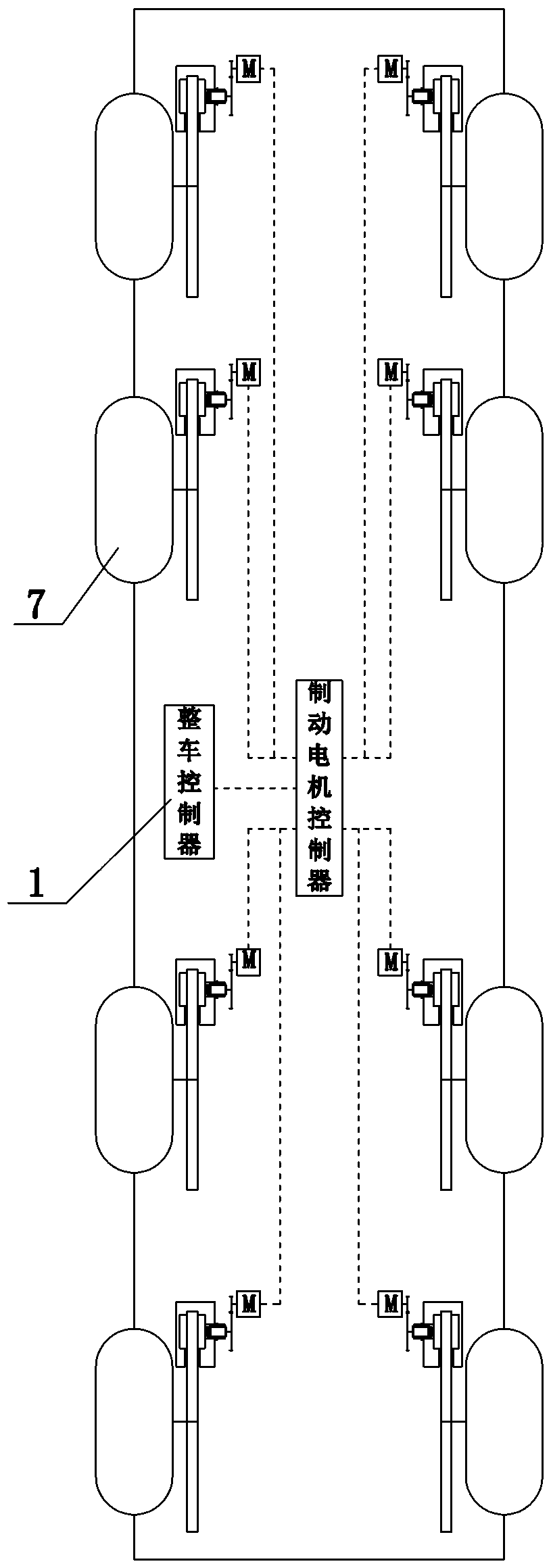
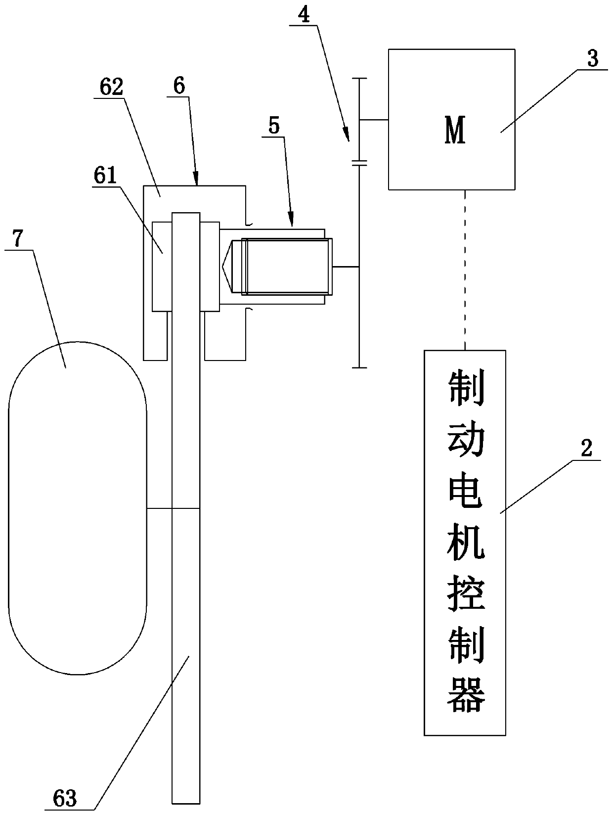
Vehicle with electromechanical brake mechanism
An electronic mechanical brake and brake motor technology, applied in the direction of brake components, brakes, vehicle components, etc., can solve the problems of difficult control of vehicle attitude, complex structure, independent and efficient control of braking torque, etc., and achieve improved braking performance. Safety, simplification of braking mechanism, and improvement of handling stability
- Summary
- Abstract
- Description
- Claims
- Application Information
AI Technical Summary
Problems solved by technology
Method used
Image
Examples
Embodiment 2
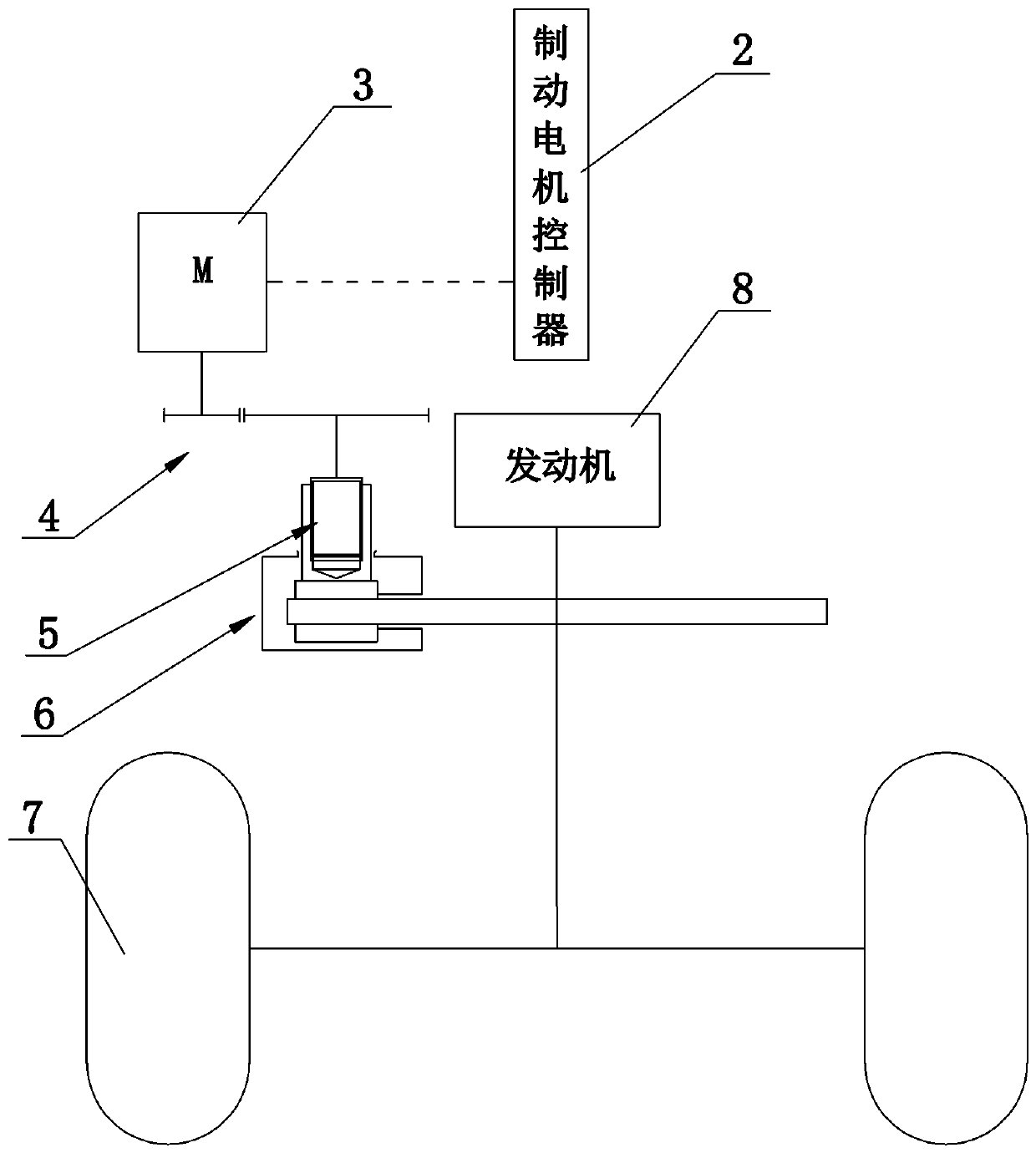
[0032] The difference between the second embodiment and the first embodiment is that it also includes a drive system, the drive system includes an engine 8, the output shaft of the engine 8 is connected to the wheel 7, the brake 6 is assembled on the output shaft of the engine 8, and the electromechanical brake The mechanism brakes the output shaft of the engine 8 through the brake 6, thereby realizing the indirect braking of two wheels at the same time. If the drive system also includes a transmission (not shown in the figure) matched with the engine 8, that is, the output shaft of the engine 8 is connected to the transmission, and the output shaft of the transmission is connected to the wheel 7, then the brake 8 is assembled on the output shaft of the transmission. The brake 8 brakes the output shaft of the transmission.
Embodiment 3
[0034] The difference between the third embodiment and the first embodiment is that it also includes a drive system, the drive system includes a drive motor 9, the output shaft of the drive motor 9 is in transmission connection with the wheel 7, and the brake 6 is assembled on the output shaft of the drive motor 9, electronically The mechanical braking mechanism brakes the output shaft of the drive motor 9 through the brake 6, thereby realizing indirect braking of two wheels at the same time. If the drive system also includes a transmission (not shown in the figure) that matches the drive motor 9, that is, the output shaft of the drive motor 9 is connected to a transmission, and the output shaft of the transmission is connected to the wheel 7, then the brake 8 is assembled on the output shaft of the transmission. , the output shaft of the transmission is braked by the brake 8 .
Embodiment 4
[0036] The difference between the fourth embodiment and the first embodiment is that it also includes a drive system, the drive system includes a distributed drive motor 10, the output shaft of the distributed drive motor 10 is connected to the wheel 7, and the brake 6 is assembled on the distributed drive motor 10, the electromechanical braking mechanism brakes the output shaft of the distributed drive motor 10 through the brake 6, thereby realizing indirect braking of a single wheel. If the drive system also includes a transmission (not shown in the figure) that matches the distributed drive motor 10, that is, the output shaft of the distributed drive motor 10 is connected to a transmission, and the output shaft of the transmission is connected to the wheel 7, then the brake 8 is assembled on the The output shaft of the transmission is braked by the brake 8 on the output shaft of the transmission.
PUM
 Abstract
Description
Claims
Application Information
 - R&D Engineer
- R&D Manager
- IP Professional
- Industry Leading Data Capabilities
- Powerful AI technology
- Patent DNA Extraction
Browse by: Latest US Patents, China's latest patents, Technical Efficacy Thesaurus, Application Domain, Technology Topic, Popular Technical Reports.
© 2024 PatSnap. All rights reserved.Legal|Privacy policy|Modern Slavery Act Transparency Statement|Sitemap|About US| Contact US: help@patsnap.com


