Electric-pneumatic composite braking control method for train

A hybrid braking and braking control technology, applied in the field of rail transit vehicles, can solve the problems of reduced braking reliability, increased brake shoe wear, large brake shoe wear, etc., to reduce signal delay, prevent braking force superposition, The effect of reducing maintenance costs

Active Publication Date: 2019-11-12
CRRC QINGDAO SIFANG ROLLING STOCK RES INST
View PDF7 Cites 12 Cited by
  • Summary
  • Abstract
  • Description
  • Claims
  • Application Information

AI Technical Summary

Problems solved by technology

[0014] (1) The delay is large, causing the train to rush and the brake shoes to wear
[0015] When electric-pneumatic hybrid braking is performed, the braking system needs to send an electric braking request signal to the traction system first, and then the traction system receives the electric braking request signal to control the output of electric braking force, and finally sends an electric braking feedback signal to the braking system , this process will bring a large delay; the large delay problem cannot be avoided when the network participates in signal transmission
A large delay will cause the superimposition of air braking and electric braking, resulting in excessive train impulse, affecting passenger comfort, and increasing brake shoe wear
[0016] (2) The signal interface is complex
[0017] The complexity of the interface indicates that the probability of failure is greatly increased. When the electric braking request signal fails, the traction system cannot obtain the electric braking demand value, so that the electric braking force cannot be normally exerted, which will affect the entire electric-pneumatic hybrid braking process. , the braking reliability of the system is reduced
[0018] (3) High requirements for real-time and reliability of the network system
If the network system fails, the electro-pneumatic hybrid braking function will not be realized
[0020] (4) Poor adaptability to trains
[0021] The way of transmission through the network system has poor adaptability to the train, and requires a high-performance train network system, and the train has corresponding communication cables and interfaces, especially for some existing models with poor network system performance.

Method used


Image

  • Electric-pneumatic composite braking control method for train
  • Electric-pneumatic composite braking control method for train
  • Electric-pneumatic composite braking control method for train

Examples


Embodiment 1

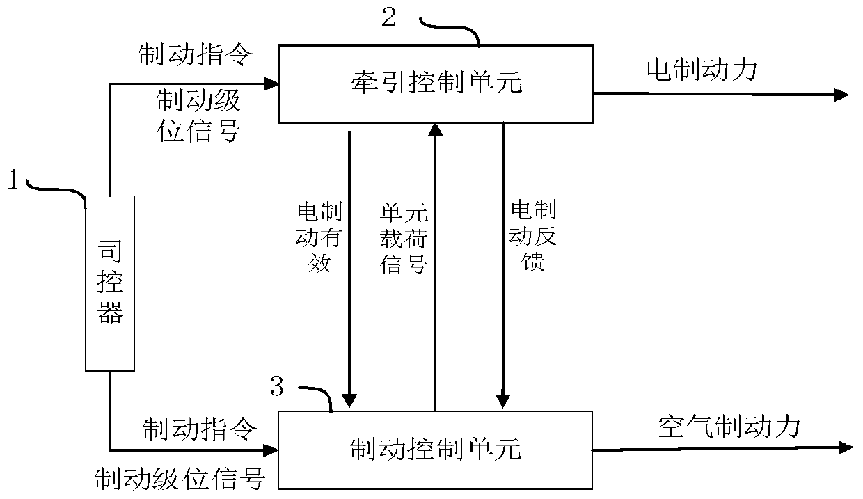
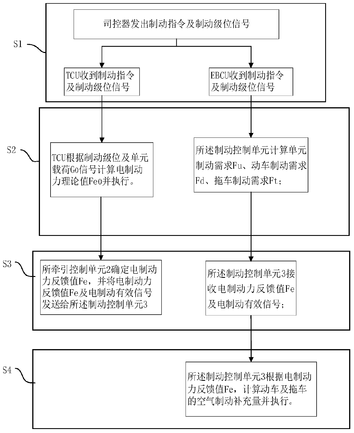
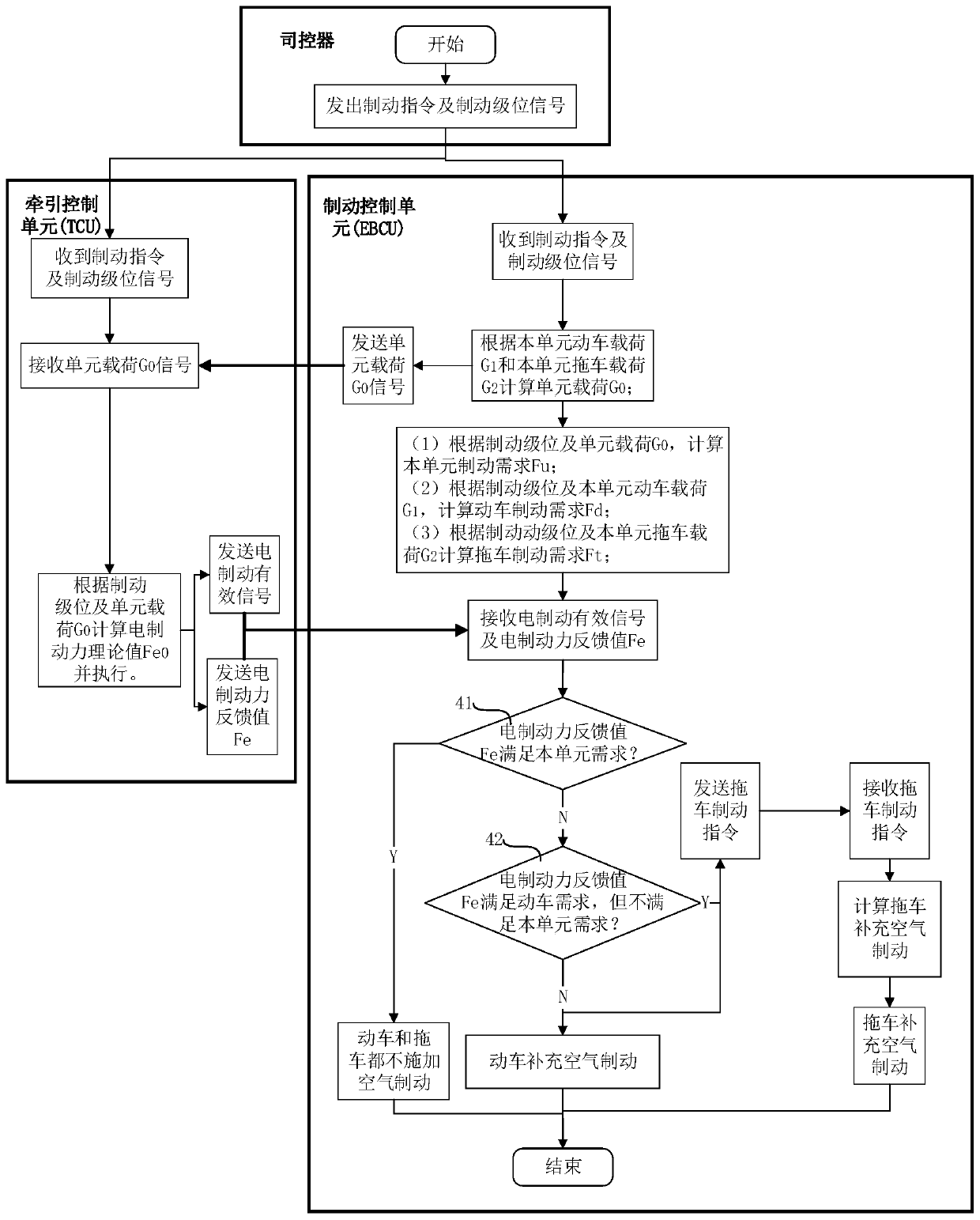
[0072] see figure 1 , the train is provided with a controller 1, and the train is divided into several motor car trailer units, and electro-pneumatic hybrid braking is carried out in each motor car trailer unit; the motor car trailer unit is provided with a traction system and a braking system; The traction system includes a traction control unit 2 (TCU), and the braking system includes a brake control unit 3 (EBCU); the controller 1 sends the traction control unit 2 (TCU) and the brake control unit 3 (EBCU) Braking command and braking level signal; the traction control unit 2 (TCU) and braking control unit 3 (EBCU) receive the braking command and braking level signal, and perform the next step of operation. Preferably, in this embodiment, the traction control unit 2 (TCU) and the brake control unit 3 (EBCU) directly perform signal interaction through electrical hard wires to realize real-time data transmission.

[0073] In this embodiment, TCU represents the traction control...

Embodiment 2

[0093] The principle of the second embodiment is the same as that of the first embodiment, which is a further specific implementation of the first embodiment, and the specific content is as follows:

[0094] Such as Figure 4-Figure 5 , the traction control unit 2 (TCU) includes an electric brake controller and an electric brake applicator coupled thereto, the traction control unit 2 (TCU) transmits information through the electric brake controller, and is controlled by the electric brake controller The brake applicator executes the relevant commands to apply the electric brake.

[0095] In this embodiment, the motor car EBCU represents the motor car brake control unit 31 , and the trailer EBCU represents the trailer brake control unit 32 .

[0096] The braking control unit 3 (EBCU) includes a motor vehicle braking control unit 31 (motor vehicle EBCU) and a trailer braking control unit 32 (trailer EBCU), and the motor vehicle braking control unit 31 (motor vehicle EBCU) inclu...

Embodiment 3

[0128] The principle of the third embodiment is the same as that of the first embodiment to the second embodiment, and the main difference is that: Figure 9-Figure 10 , in this embodiment, the motor vehicle braking control unit 31 presets the normal range of the electric braking force feedback value, and the electric braking force feedback value Fe exceeds the preset normal range of the electric braking force feedback value (below or higher than the normal range) , and last for a preset time, it indicates that the feedback signal is abnormal. That is, when the electric brake feedback signal exceeds the physical limit (lower or higher than the normal range) for a certain period of time, it indicates that the feedback signal is abnormal. At this time, the motor vehicle brake control unit 31 (motor vehicle EBCU) sends an electric brake removal signal to the traction control Unit 2 (TCU), the traction control unit 2 (TCU) receives the electric brake removal signal, and cuts off t...


PUM


Abstract

The invention discloses an electric-pneumatic composite braking control method for a train. The train is divided into a plurality of bullet train trailer units, and electric-pneumatic composite braking is performed in each bullet train trailer unit; a traction control unit and a brake control unit are arranged on the bullet train trailer unit; the control method comprises the following steps thatS1, the traction control unit and the brake control unit receive a brake instruction and a brake level signal; S2, the traction control unit calculates an electric braking force theoretical value Fe0and executes electric braking force; the brake control unit calculates the unit brake requirement Fu, the bullet train brake requirement Fd and the trailer brake requirement Ft; S3, the traction control unit determines an electric braking force feedback value Fe, and sends the electric braking force feedback value Fe and an electric braking effective signal to the brake control unit; S4, the brakecontrol unit calculates the air brake supplementing amount of the bullet train and the trailer and executes air brake; signal delay is effectively reduced, the real-time performance of electric-pneumatic composite braking is enhanced, and the response speed of electric-pneumatic braking is increased.

Description

technical field [0001] The invention belongs to the field of rail transit vehicles, and specifically proposes an electro-pneumatic hybrid braking control method for trains. Background technique [0002] At present, the braking force of most urban rail trains comes from the electric braking force provided by the traction system and the air braking force provided by the braking system. The common braking and fast braking functions of the train all adopt the electric-pneumatic hybrid braking method. The braking force of the train is shared by electric braking and air braking, which requires an electro-pneumatic hybrid braking method to manage the coordination between the two braking forces. [0003] At present, there are mainly several ways of electro-pneumatic hybrid braking: [0004] (1) Calculated and controlled by the braking system [0005] The braking system calculates the total braking force demand of the train or unit according to the braking level and train load, and...

Claims


Application Information

Patent Timeline
Patent Type & Authority Applications(China)
IPC IPC(8): B60T13/58B61H11/14B61C17/12
CPCB60T13/58B61C17/12B61H11/14
Inventor 赵欣董建峰孙全涛崔晓军李莉张乾乾
Owner CRRC QINGDAO SIFANG ROLLING STOCK RES INST
Why Eureka
Try Eureka