Electronic brake system and method for operating the same

a technology of electronic brakes and electronic components, applied in the direction of braking systems, braking components, transportation and packaging, etc., can solve the problems of electronic brake systems entering abnormal operation modes, affecting the safety of drivers and passengers riding in vehicles, and affecting the performance of electronic brake systems. , to achieve the effect of improving product durability, improving product performance and operation stability

Active Publication Date: 2019-04-04
HL MANDO CORP
View PDF0 Cites 13 Cited by
  • Summary
  • Abstract
  • Description
  • Claims
  • Application Information

AI Technical Summary

Benefits of technology

[0014]It is another aspect of the present disclosure to provide an electronic brake system for improving performance and operational stability of a product, and a method for operating the same.
[0015]It is another aspect of the present disclosure to provide an electronic brake system for improving product durability by reducing load applied to electronic components, and a method for operating the same.
[0016]It is another aspect of the present disclosure to provide an electronic brake system for reducing the size of a product and the number of electronic components of the product, and a method for operating the same.

Problems solved by technology

Since the electronic brake system can be electrically operated and controlled as described above, the electronic brake system can implement complicated and various braking actions.
However, if technical issues occur in electronic components of the electronic brake system, hydraulic pressure needed for braking is not stably formed, there is a high possibility of threatening the safety of a driver and passengers who ride in the vehicle.
Therefore, if any one of various electronic components embedded in the vehicle abnormally operates or if it is impossible to control the abnormal electronic component, the electronic brake system enters an abnormal operation mode.
That is, during the abnormal operation mode of the electronic brake system, hydraulic pressure needed for braking needs to be immediately formed in response to a pedal effort of the brake pedal depressed by the driver, and the hydraulic pressure needs to be directly supplied to wheel cylinders.
However, during regenerative braking, this regenerative braking mode may unavoidably affect distribution of brake force applied to a plurality of vehicle wheels, such that oversteer, understeer, or slippage of the wheels may occur, resulting in reduction of vehicle driving stability.

Method used


Image

  • Electronic brake system and method for operating the same
  • Electronic brake system and method for operating the same
  • Electronic brake system and method for operating the same

Examples


first embodiment

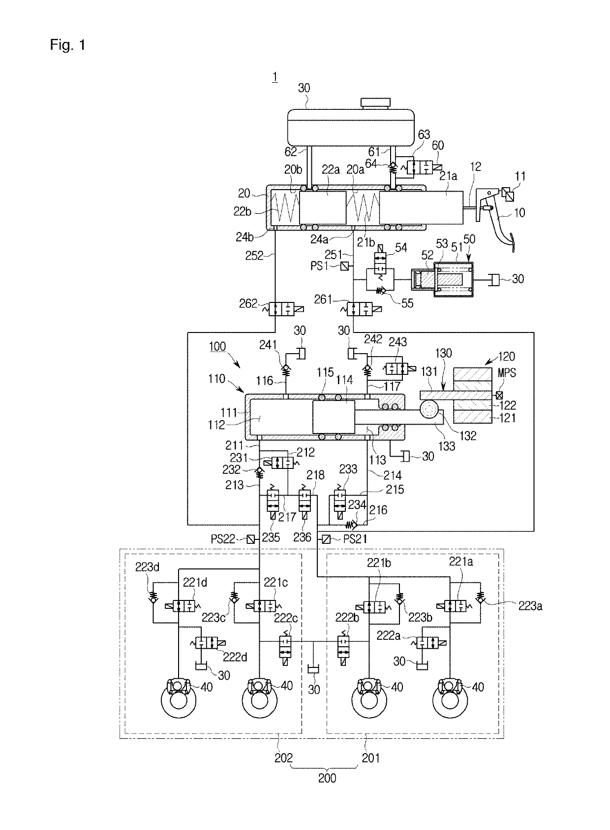
[0059]FIG. 1 is a hydraulic circuit diagram illustrating an electronic brake system 1 according to the present disclosure.

[0060]Referring to FIG. 1, the electronic brake system 1 may include a master cylinder 20 to pressurize and discharge a pressure medium (e.g., brake fluid) included therein according to a pedal effort of a brake pedal 10 depressed by a driver of a vehicle, a reservoir 30 formed to communicate with the master cylinder 20 to store the pressure medium, one or more wheel cylinders 40 to perform braking of respective wheels RR, RL, FR, and FL upon receiving hydraulic pressure generated by the pressure medium, a simulation device 50 to provide the driver with reaction force corresponding to a pedal effort of the brake pedal 10, a hydraulic-pressure supply device 100 to generate hydraulic pressure of a pressure medium by mechanically operating upon receiving an electric signal indicating the driver's braking intention from a pedal displacement sensor 11 sensing displace...

second embodiment

[0209]An electronic brake system 2 according to the present disclosure will hereinafter be described.

[0210]In the following detailed description of the electronic brake system 2 according to the second embodiment, the remaining parts other than other constituent elements denoted by different reference numbers not shown in the electronic brake system 1 of the first embodiment are identical to those of the electronic brake system 1 of the first embodiment, and as such a detailed description thereof will herein be omitted to avoid redundant description thereof.

[0211]FIG. 12 is a hydraulic circuit diagram illustrating the electronic brake system 2 according to a second embodiment of the present disclosure.

[0212]Referring to FIG. 12, a first hydraulic passage 311 of the electronic brake system 2 according to the second embodiment may be provided to connect the first pressure chamber 112 to the first and second hydraulic circuits 201 and 202, and the first hydraulic passage 311 may be bra...


PUM


Abstract

An electronic brake system and a method for operating the same are disclosed. The electronic brake system includes a hydraulic-pressure supply device and a hydraulic-pressure control unit. The hydraulic-pressure supply device operates a hydraulic piston using an electric signal corresponding to a displacement of a brake pedal, and thus generates hydraulic pressure. The hydraulic-pressure control unit controls hydraulic pressure of a pressure medium supplied to individual wheel cylinders. The electronic brake system controls a plurality of valves mounted to the hydraulic-pressure control unit, and thus performs a normal operation mode, an abnormal operation mode, a regenerative braking mode, and an inspection mode using the valves.

Description

CROSS-REFERENCE TO RELATED APPLICATION[0001]This application is based on and claims priority under 35 U.S.C. § 119 to Korean Patent Application Nos. 2017-0127433 and 2017-0127510, respectively filed on Sep. 29, 2017 and Sep. 29, 2017 in the Korean Intellectual Property Office, the disclosure of which is incorporated by reference in its entirety.BACKGROUND1. Field[0002]Embodiments of the present disclosure relate to an electronic brake system and a method for operating the same, and more particularly to an electronic brake system for generating braking force using an electrical signal corresponding to a displacement of a brake pedal, and a method for operating the same.2. Description of the Related Art[0003]A brake system for braking of a vehicle is essentially mounted to a vehicle, and various brake systems have recently been proposed to secure safety of a driver and passengers.[0004]Conventionally, when a driver depresses a brake pedal, a conventional brake system is designed to su...

Claims


Application Information

Patent Timeline
Patent Type & Authority Applications(United States)
IPC IPC(8): B60T13/68B60T7/04B60T13/14B60T13/66
CPCB60T13/686B60T7/042B60T13/145B60T13/662B60T8/4081B60T13/745B60T2270/404
Inventor JEONG, HYOJINKIM, JONG WOOK
Owner HL MANDO CORP
Why Eureka
Try Eureka