Retarder Controlling Device and Method

a control device and a technology of a retarder, applied in the direction of braking systems, instruments, analogue processes for specific applications, etc., can solve the problems of deteriorating the deceleration effect, unable to use to decelerate a vehicle, and unable to continue safe operation of the vehicle, so as to achieve reliable and effective braking

Inactive Publication Date: 2008-03-20
KOMATSU LTD
View PDF12 Cites 13 Cited by
  • Summary
  • Abstract
  • Description
  • Claims
  • Application Information

AI Technical Summary

Benefits of technology

[0017] According to the present invention, it is possible to provide a retarder control

Problems solved by technology

The deceleration effect can thus be deteriorated.
This cannot be used to decelerate a vehicle running on flat ground in the state that an accelerator is 100% off.
For instance, this cannot be used to continue safe

Method used


Image

  • Retarder Controlling Device and Method
  • Retarder Controlling Device and Method
  • Retarder Controlling Device and Method

Examples


Embodiment Construction

[0032] Embodiments of the present invention will be described below in detail with reference to the drawings.

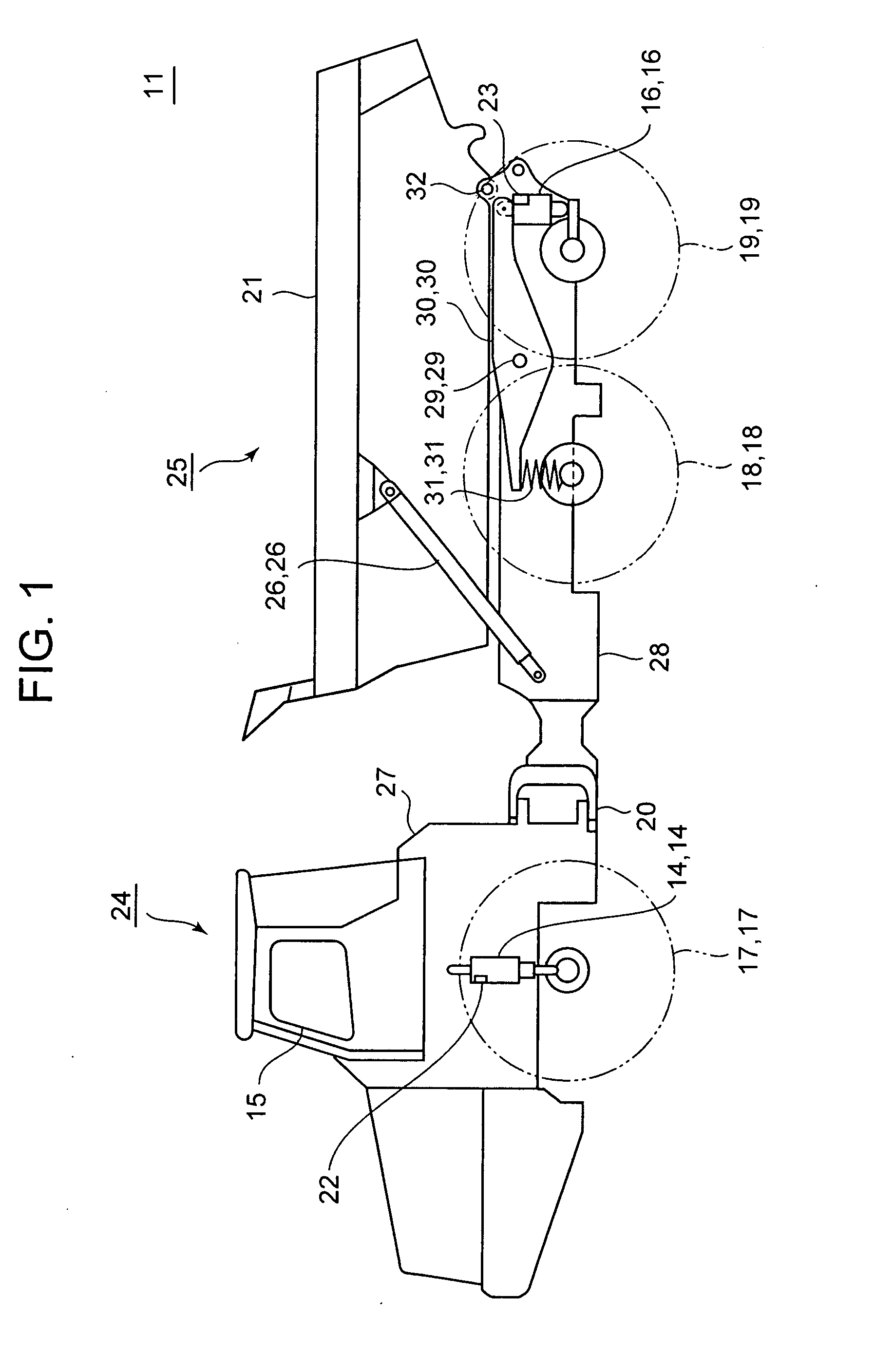
[0033]FIG. 1 shows a side view of an articulated dump truck 11 (hereinafter, called the dump truck 11). The dump truck 11 has a front frame 27 supporting a front body 24 and a rear frame 28 supporting a rear body 25. The rear frame 28 is coupled to the front frame 27 by a coupling device 20 so as to be bent to the right and left of the traveling direction and to be swingably about the traveling direction as a rotating axis.

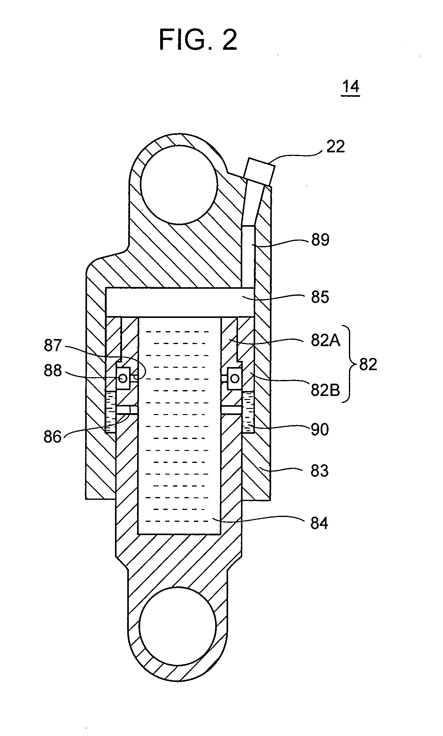
[0034] The front frame 27 has a cab 15 mounted thereon. The front frame 27 is fitted with a pair of right and left front wheels 17 via front suspensions 14, 14.

[0035] A body 21 loaded with a load such as earth and sand is mounted above the rear frame 28. The body 21 is rotated in the up-and-down direction about a rear body pin 32 by expansion and contraction of lift cylinders 26, 26.

[0036] Right and left equalizer bars 30, 30 are rotatably engaged to th...


PUM


Abstract

There is provided a retarder control device which is simple in constitution and can reliably apply braking. An engine rotational speed detector detects an engine rotational speed, gear step detection means detects a gear step of a transmission, an accelerator operation detector detects the operated state of an accelerator, and a retarder controller previously stores automatic braking amount determination data representing the relation between the engine rotational speed and the automatic braking amount of a retarder corresponding to each gear step of the transmission and controls the retarder according to the automatic braking amount of the retarder calculated from the automatic braking amount determination data based on the detected engine rotational speed and gear step of the transmission when the accelerator is judged to be off from the detected operated state of the accelerator.

Description

BACKGROUND OF THE INVENTION [0001] 1. Field of the Invention [0002] The present invention relates to a retarder control device and control method. [0003] 2. Description of the Related Art [0004] A vehicle such as a dump truck is equipped with an auxiliary braking device for braking so as to prevent a vehicle speed from being excessive when a vehicle goes down a long slope. There is known an auxiliary braking device, being called an exhaust brake, that throttles an exhaust throttle valve provided in an exhaust pipe to increase exhaust resistance when an exhaust gas is exhausted from an engine, thereby obtaining a braking force (for instance, see Patent Document 1). [0005] There is also known an auxiliary braking device called a retarder. This transmits an instruction to a braking device or a retarder braking device provided separately from the braking device and controls a vehicle speed to be constant (for instance, see Patent Document 2). [Patent Document 1] Japanese Patent Applica...

Claims


Application Information

Patent Timeline
IPC IPC(8): B60T10/00
CPCB60T10/00B60T10/02Y10T477/69Y10T477/675Y10T477/647Y10T477/816B60T8/17B60T13/585B60W30/146
Inventor NAKANISHI, HITOSHIOBARA, SACHIOSAWAFUJI, SATOSHI
Owner KOMATSU LTD
Why Eureka
Try Eureka