

Automatic textile fiber cloth dividing and cutting machine
A technology for textile fibers and slitting machines, which is applied in the direction of winding strips, thin material handling, transportation and packaging, etc., can solve the problems of delayed production time, reduced work efficiency, long downtime, etc. The effect of working efficiency and reducing time loss
- Summary
- Abstract
- Description
- Claims
- Application Information
AI Technical Summary
Problems solved by technology
Method used
Image

Examples
specific Embodiment approach 1
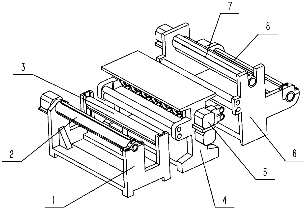
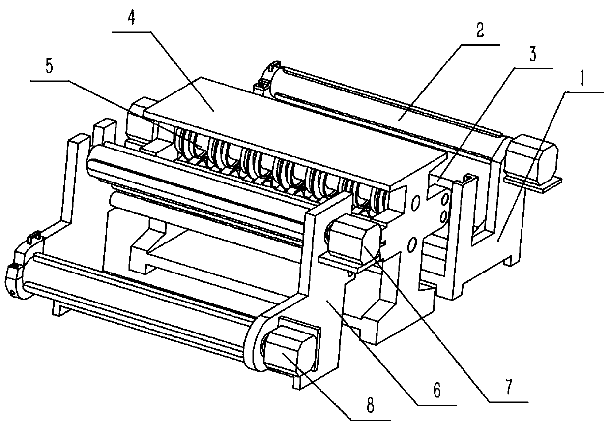
[0040] Combine below Figure 1-18 Describe this embodiment, an automatic slitting machine for textile fiber cloth, including a support mechanism I1, a support mechanism II4, and a support mechanism III6, and the support mechanism I1, support mechanism II4, and support mechanism III6 are sequentially arranged on the ground from front to back, The textile fiber cloth automatic slitting machine also includes a cloth feeding mechanism 2, a tensioning mechanism 3, a cutting mechanism 5, a cloth rolling mechanism I7 and a cloth rolling mechanism II8, and the cloth feeding mechanism 2 is fixedly connected to the front end of the supporting mechanism I1. side, the tensioning mechanism 3 is slidably connected to the rear end of the support mechanism I1, the cutting mechanism 5 is rotatably connected to the support mechanism II4, and the cloth rolling mechanism I7 is fixedly connected to the upper side of the front end of the support mechanism III6. The cloth rolling mechanism II8 is fi...
specific Embodiment approach 2
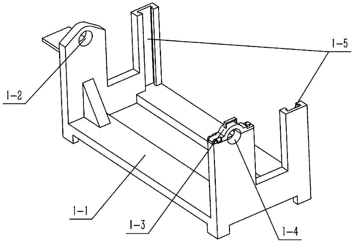
[0042] Combine below Figure 1-18 Describe this embodiment, this embodiment will further explain the first embodiment, the support mechanism I1 includes a support frame 1-1, a rotating hole I1-2, a fixed frame 1-3, a semicircular groove I1-4 and a slide rail 1-5 , the left and right sides of the upper front end of the support frame 1-1 are respectively provided with a rotating hole I1-2 and a semicircular groove I1-4, and the fixed frame 1-3 is hinged on the left side of the upper front end of the support frame 1-1, so The fixed frame 1-3 is closed with the semicircular groove I1-4 to form a round hole I, and the two slide rails 1-5 are provided with two slide rails 1-5 respectively arranged inside the rear end of the support frame 1-1. On the left and right sides, the two ends of the cloth supply mechanism 2 are respectively fixedly connected in the rotating hole I1-2 and the above-mentioned circular hole I, and the two ends of the tightening mechanism 3 are respectively slid...
specific Embodiment approach 3
[0044] Combine below Figure 1-18 Describe this embodiment, this embodiment will further explain the second embodiment, the cloth supply mechanism 2 includes a motor I2-1, a rotating roller I2-2, a bearing I2-3, a chute I2-4, and a sliding bar I2-5 and spring I2-6, two bearings I2-3 are provided, and the two bearings I2-3 are respectively fixedly connected to the left and right ends of the rotating roller I2-2, and the two bearings I2-3 are respectively fixedly connected to the rotating In the hole I1-2 and the above-mentioned round hole I, the motor I2-1 is fixedly connected to the support frame 1-1, and the output shaft of the motor I2-1 is fixedly connected to the rotating roller I2-2, and the chute I2- 4 There are three sets, three chute I2-4 are arranged on the rotating roller I2-2 in the circumferential direction, and three slide bars I2-5 are set, and the three slide bars I2-5 are respectively slidably connected to the three chute I2 -4, the inner end of each sliding b...
PUM
 Abstract
Description
Claims
Application Information