
Lifting equipment for power equipment

A lifting device and power equipment technology, applied in the direction of lifting devices, lifting frames, etc., can solve the problems of laborious installation and disassembly, large volume, etc., and achieve the effects of convenient maintenance and repair, reducing horizontal space occupation, and increasing stability

Inactive Publication Date: 2020-07-28
杨明清
View PDF6 Cites 4 Cited by
  • Summary
  • Abstract
  • Description
  • Claims
  • Application Information

AI Technical Summary

Problems solved by technology

[0004] The purpose of the present invention is to solve the disadvantages in the prior art that when the electric equipment is in use, it is laborious to install and disassemble due to its large volume and heavy weight, and proposes a lifting device for electric equipment

Method used


Image

  • Lifting equipment for power equipment
  • Lifting equipment for power equipment
  • Lifting equipment for power equipment

Examples


Embodiment 1

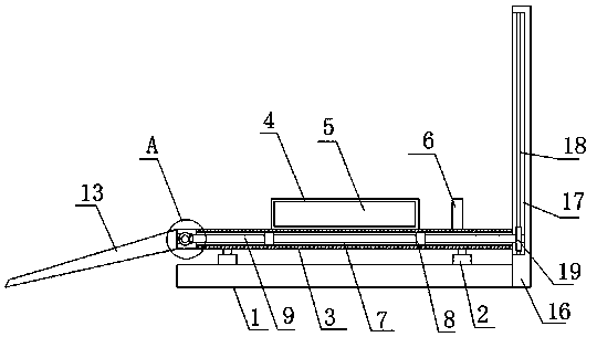
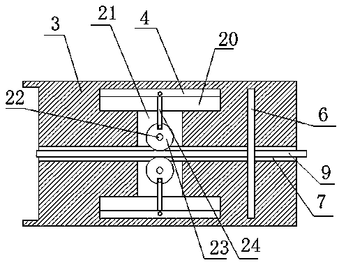
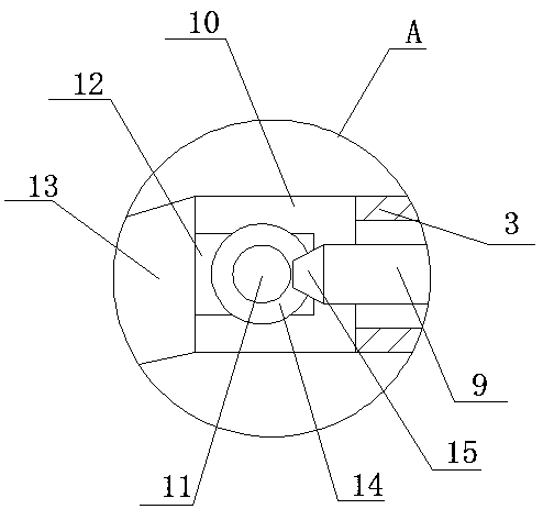
[0030] refer to Figure 1-5 , a lifting device for electric equipment, comprising a base plate 1, a lifting plate 3 is arranged above the base plate 1, a rotating groove 10 is opened on one side of the lifting plate 3, a rotating shaft 11 is installed in the rotating groove 10, and the rotating shaft Two connecting blocks 12 are fixedly installed on the outer side of 11, and the same inclined plate 13 is fixedly installed on one side of the two connecting blocks 12, and two grooves 20 are opened on the top of the lifting plate 3, and both grooves 20 slide Sliding plate 4 is installed, and splint 5 is slidingly installed on the side of two sliding plates 4 close to each other, baffle plate 6 is installed on the top of lifting plate 3, vertical plate 16 is fixedly installed on one side of bottom plate 1, and one side of vertical plate 16 is opened There is a mounting groove 17, a rack 18 is fixedly installed on the side wall of the mounting groove 17, a gear 19 is meshed on the ...

Embodiment 2

[0041] refer to Figure 1-5 , a lifting device for electric equipment, comprising a base plate 1, a lifting plate 3 is arranged above the base plate 1, a rotating groove 10 is opened on one side of the lifting plate 3, a rotating shaft 11 is installed in the rotating groove 10, and the rotating shaft The outer side of 11 is fixed with two connecting blocks 12 by bolts, and one side of the two connecting blocks 12 is fixed with the same inclined plate 13 by bolts, and the top of lifting plate 3 is provided with two grooves 20, two grooves Sliding boards 4 are installed inside the 20, splints 5 are slidingly installed on the sides where the two sliding boards 4 are close to each other, baffles 6 are installed on the top of the lifting board 3, and vertical boards 16 are installed on one side of the bottom board 1 through bolts. One side of plate 16 is provided with mounting groove 17, and the side wall of mounting groove 17 is fixed with rack 18 by bolt, and gear 19 is meshed on...


PUM


Abstract

The invention belongs to the field of lifting equipment, and particularly relates to lifting equipment for power equipment. The following scheme is provided at present for the problem that when existing power equipment is used, due to the fact that the size is large, and the weight is large, mounting and dismounting are strenuous. According to the scheme, the lifting equipment comprises a bottom plate, wherein a lifting plate is mounted above the bottom plate, a rotating groove is formed in one side of the lifting plate, a rotating shaft is rotationally mounted in the rotating groove, two connecting blocks are fixedly mounted on the outer side of the rotating shaft, the same inclined plate is fixedly mounted on one sides of the two connecting blocks, two grooves are formed in the top of the lifting plate, and sliding plates are slidably mounted in the two grooves. According to the lifting equipment for the power equipment, the power equipment can be conveniently moved onto the liftingplate or moved away from the lifting plate, the power equipment can be conveniently maintained and overhauled, and meanwhile, the inclined plate can be folded when the lifting plate is lifted, the transverse occupied space is reduced, the power equipment can be fixed, and the stability of the power equipment during use is improved.

Description

technical field [0001] The invention relates to the technical field of lifting equipment, in particular to a lifting device for electric equipment. Background technique [0002] Power equipment mainly includes power generation equipment and power supply equipment. Power generation equipment mainly includes power plant boilers, steam turbines, gas turbines, water turbines, generators, transformers, etc. [0003] When the existing power equipment is in use, due to its large size and heavy weight, it is laborious to install and disassemble it. Therefore, we propose a lifting device for power equipment to solve the above problems. Contents of the invention [0004] The purpose of the present invention is to solve the disadvantages of large volume, heavy weight, laborious installation and disassembly of electric equipment in the prior art, and propose a lifting device for electric equipment. [0005] In order to achieve the above object, the present invention adopts the follow...

Claims


Application Information

Patent Timeline
Patent Type & Authority Applications(China)
IPC IPC(8): B66F7/20B66F7/28
CPCB66F7/20B66F7/28
Inventor 杨明清
Owner 杨明清
Learn More