Blow-out prevention valve in double-layer pipe

A technology of internal blowout prevention and double-layer pipes, which is applied in the direction of wellbore/well valve device, wellbore/well components, sealing/isolation, etc., can solve problems such as inability to achieve effective control, and improve drilling efficiency, The effect of saving time and preventing well kick or blowout accident

Active Publication Date: 2020-07-28
SOUTHWEST PETROLEUM UNIV
View PDF6 Cites 7 Cited by
  • Summary
  • Abstract
  • Description
  • Claims
  • Application Information

AI Technical Summary

Problems solved by technology

[0003] The drilling and mining process of double-layer pipe puts forward new requirements for related equipment. The existing blowout preventer can seal the drill pipe and the annulus of the well wall or cut the drill pipe to fully seal the wellhead. After using double-layer pipe, The return liquid is returned from the inside of the pipe without going through the drill pipe and the annulus of the borehole wall, so it is impossible to effectively control the annulus of the inner and outer pipes of the double-layer pipe and the two channels of the inner pipe

Method used


Image

  • Blow-out prevention valve in double-layer pipe
  • Blow-out prevention valve in double-layer pipe
  • Blow-out prevention valve in double-layer pipe

Examples


Embodiment 1

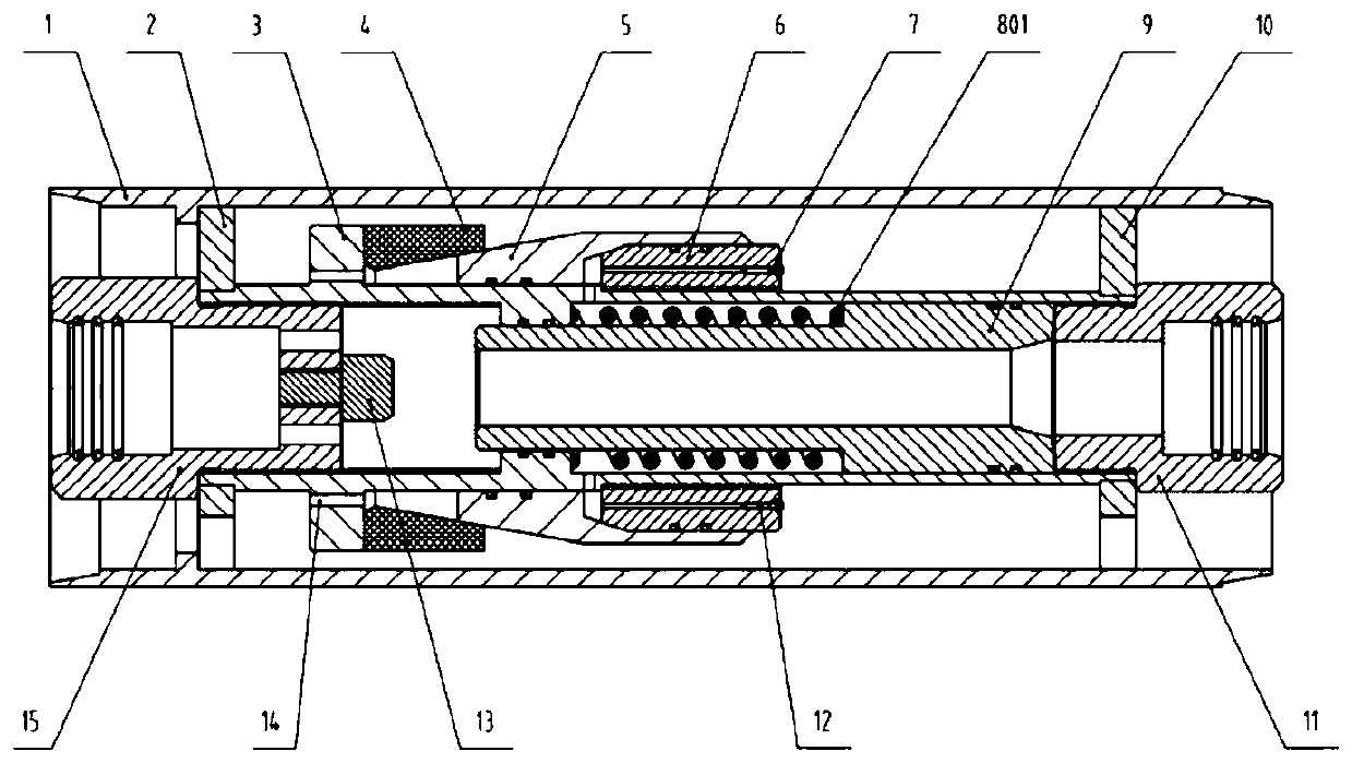
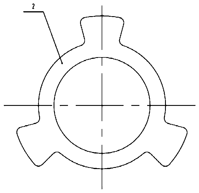
[0021] Embodiment 1 of a double-layer pipe blowout preventer valve, such as figure 1 As shown, the device includes a rubber core 4, a piston 5, a valve seat 6, a differential pressure sliding sleeve 9, a support plate, an inner pipe 3, an outer pipe 1, an upper joint 15 of the inner pipe and a lower joint 11 of the inner pipe; The differential sliding sleeve 9 is located in the inner tube cavity, and its initial position is pushed against the lower joint 11 of the inner tube by the elastic force of the spring 801; the rubber core 4 and the piston 5 are located on the outer wall of the inner tube 3, and the rubber core 4 is placed in turn On the outer step of the inner pipe, put the piston 5 into it and finally fix it by the threaded cooperation between the valve seat 3 and the inner pipe; the outer step of the inner pipe is arranged with 6 pressure relief ports 14 along the circumference for discharging the rubber core 4, The drilling fluid in the cavity formed by the piston 5...

Embodiment 2

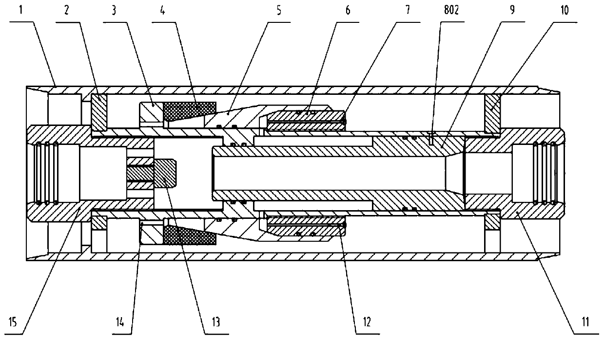
[0027] The structure and working principle of this embodiment are basically the same as that of Embodiment 1, the difference is that image 3 As shown, in this embodiment, the shear pin 802 is used to replace the spring 801 to position the initial position of the differential pressure sleeve 9. When a well kick or blowout occurs, the high-pressure fluid pushes the differential pressure sleeve 9 to move the shear pin 802 Cut off, so that the pressure differential sliding sleeve 9 cooperates with the plugging block 13 to close the inner tube 3. After using the shear pin 802, the tool cannot be opened by itself. It is necessary to lift the tool out of the well, replace the shear pin 802, and run it again.

[0028] Other structural principles and motion processes of this embodiment are the same as those of Embodiment 1, and will not be repeated here.


PUM


Abstract

The invention provides a blow-out prevention valve in a double-layer pipe. The device comprises a piston, a rubber core, a valve seat, a differential pressure sliding sleeve, a supporting plate, an inner pipe, an outer pipe, an upper joint of the inner pipe and a lower joint of the inner pipe. The differential pressure sliding sleeve is located in an inner pipe cavity and is positioned by an innerpipe step and the lower joint of the inner pipe; the piston and the rubber core are located on the outer wall of the inner pipe and are positioned by the inner pipe step and the valve seat, and a cavity formed by the piston, the valve seat and the outer wall of the inner pipe communicates with a cavity formed by the differential pressure sliding sleeve and the inner pipe; and the supporting plateis fixed to the inner pipe step through the upper joint of the inner pipe and the lower joint of the inner pipe, and the inner pipe is positioned by an outer pipe step. According to the blow-out prevention valve in the double-layer pipe, self-closing can be realized in case of overflow during double-layer pipe drilling or mining, the occurrence of well kick or blowout accidents is effectively prevented, and power fluid can be used for reopening after the environment in the well is stable to continue drilling or mining, time is saved, the drilling and milling efficiency is improved.

Description

technical field [0001] The invention relates to the technical field of double-tube drilling and mining blowout prevention, in particular to a double-tube drilling and mining blowout preventer. Background technique [0002] The double-layer pipe drilling and production method is to use double-layer pipe and its supporting equipment for drilling and production. It is currently applicable to double-gradient drilling and hydrate solid-state fluidization mining. It is one of the frontier topics in the current energy field and is mainly used in deep sea. Development of oil and gas and shallow hydrates. The difference from conventional drilling is that the double-layer pipe forms two channels through the inner pipe and the annulus of the inner and outer pipes. The annulus of the inner and outer pipes is the drilling fluid injection channel, and the inner pipe is the drilling fluid return channel, thus forming an independent loop circulation channel. [0003] The drilling and minin...

Claims


Application Information

Patent Timeline
Patent Type & Authority Applications(China)
IPC IPC(8): E21B34/08
CPCE21B34/08
Inventor 钟林余兴勇王国荣刘清友周守为李中付强何玉发李清平胡刚李炎军刘和兴王川唐洋
Owner SOUTHWEST PETROLEUM UNIV
Why Eureka
Try Eureka