Axial flow fan with adjustable blades

An axial-flow, adjustable technology, applied in the direction of mechanical equipment, non-variable pumps, machines/engines, etc., can solve the problems of not being able to meet the requirements of use, not being able to adjust the blade angle, increasing production costs, etc., and achieve flexible operation Effect

Active Publication Date: 2020-07-28
上海应达风机股份有限公司
View PDF6 Cites 2 Cited by
  • Summary
  • Abstract
  • Description
  • Claims
  • Application Information

AI Technical Summary

Problems solved by technology

[0003] refer to figure 1 , figure 1 It is a schematic diagram of the structure of the existing axial flow fan. The blades 2 of the existing axial flow fan are directly fixed on the hub 1. The blade has only one angle, and the angle of the blade cannot be adjusted. If different angles of air volume and The wind direction can only be met if it is specially designed or equipped with blades with other angles
[0004] The above-mentioned existing technical solutions have the following defects: the angle of the blades cannot be adjusted according to different air volume requirements in different environments, and cannot meet the requirements of use; preparing blades with different angles increases the production cost

Method used


Image

  • Axial flow fan with adjustable blades
  • Axial flow fan with adjustable blades
  • Axial flow fan with adjustable blades

Examples


Embodiment Construction

[0041] The present invention will be described in further detail below in conjunction with the accompanying drawings.

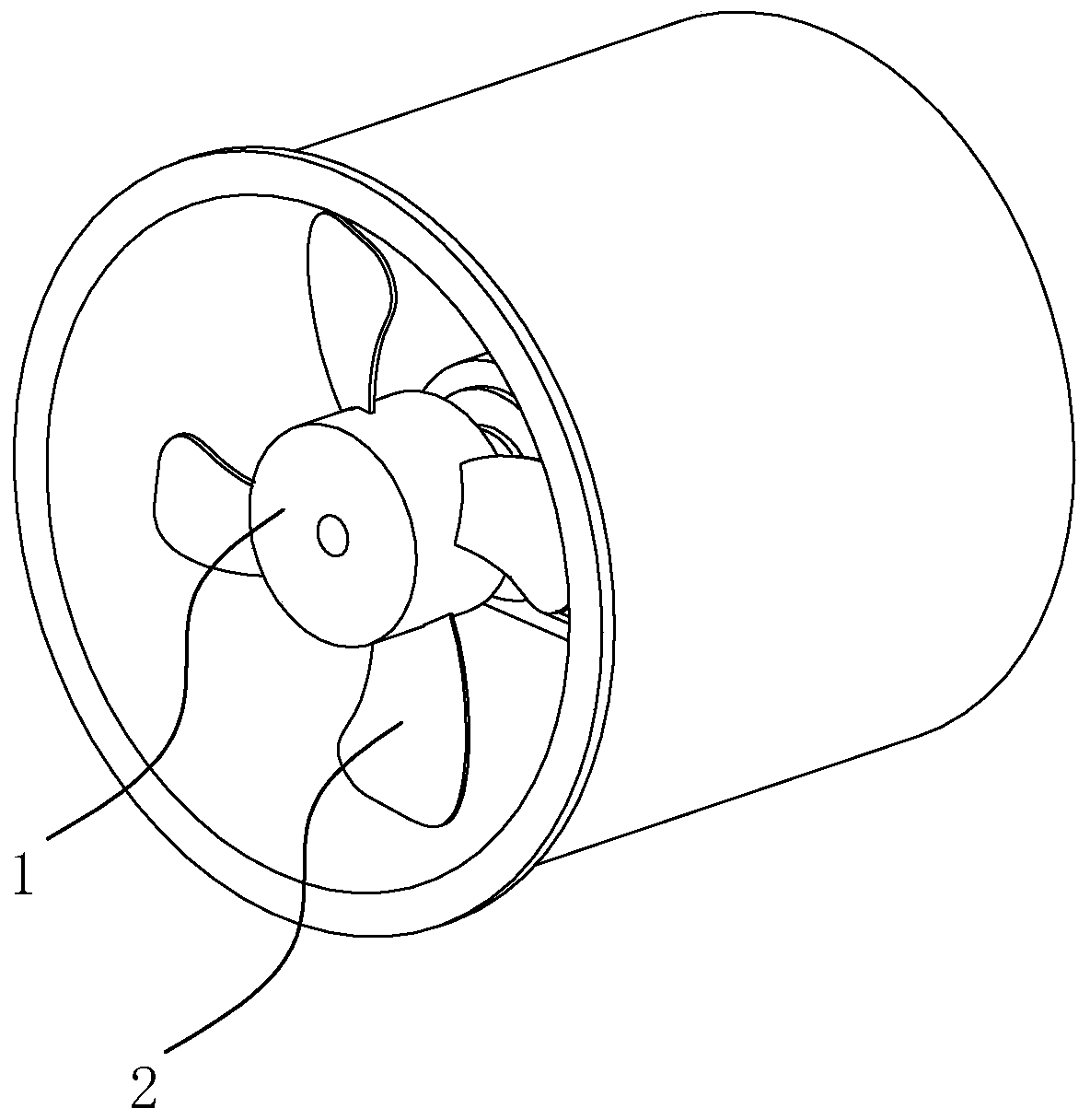
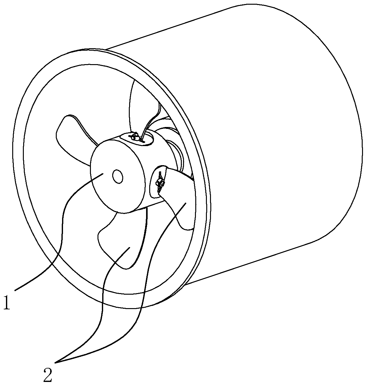
[0042] refer to figure 2 with image 3 , is an axial flow fan with adjustable blades disclosed by the present invention, including a drive motor, an impeller and a protective cover, the impeller consists of a hub 1 and four blades 2, a bottom plate is provided in the protective cover, and the drive motor is installed on the bottom plate Above, the rotating shaft of the driving motor is connected to the hub 1, and the blades 2 are evenly inserted on the hub 1 through the adjusting device 3.

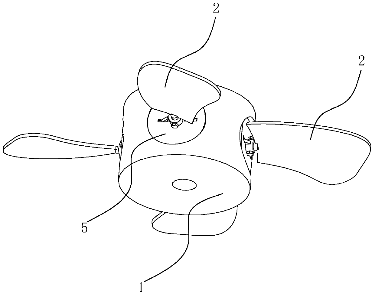
[0043] refer to image 3 with Figure 4 , the axial flow fan includes four adjustment devices 3, four grooves 11 are opened on the hub 1, and the adjustment devices 3 are flexibly connected in the grooves 11, refer to Figure 5 , the bottom of the blade 2 is provided with an insertion rod 4, which is fixedly connected to the blade, and the insertion rod 4 is inserted...


PUM


Abstract

The invention relates to an axial flow fan with adjustable blades, particularly relates to the technical field of axial flow fans, and provides an axial flow fan capable of directly adjusting the blade angle to meet the use requirements. The axial flow fan comprises a driving motor, an impeller, a protective cover and at least three adjusting devices for adjusting the blade angle, wherein the blades are installed on a hub through the adjusting devices; each adjusting device comprises a ratchet wheel and a mounting sleeve, and the mounting sleeve is fixedly connected to the upper end face of the ratchet wheel; at least three grooves for containing the adjusting devices are formed in the hub, the adjusting devices are movably connected into the grooves, and pawls matched with the ratchet wheels are arranged on the bottom faces of the grooves; and inserting rods are arranged at the bottoms of the blades, the inserting rods are fixedly connected with the blades, the inserting rods are inserted into the mounting sleeves to enable the blades to be connected with the adjusting devices, and the angles of the blades are adjusted through rotation of the ratchet wheels. According to the axialflow fan, the ratchet wheels rotate to drive the blades to rotate, the pawls fix the ratchet wheels, and the effect of adjusting the air volume and the air direction is achieved by directly adjustingthe angles of the blades.

Description

technical field [0001] The invention relates to the technical field of axial flow fans, in particular to an axial flow fan with adjustable blades. Background technique [0002] The axial flow fan is the airflow in the same direction as the axis of the fan blade (that is, the flow direction of the wind is parallel to the axis). For example, electric fans and air conditioner fans are axial flow fans. [0003] refer to figure 1 , figure 1 It is a schematic diagram of the structure of the existing axial flow fan. The blades 2 of the existing axial flow fan are directly fixed on the hub 1. The blade has only one angle, and the angle of the blade cannot be adjusted. If different angles of air volume and The wind direction can only be met if it is specially designed or equipped with blades with other angles. [0004] The above-mentioned existing technical solutions have the following defects: the angle of the blades cannot be adjusted according to the requirements of different a...

Claims


Application Information

Patent Timeline
Patent Type & Authority Applications(China)
IPC IPC(8): F04D29/32F04D27/00
CPCF04D27/002F04D29/325
Inventor 应德池
Owner 上海应达风机股份有限公司
Why Eureka
Try Eureka