Large high-temperature releasing valve capable of rapidly replacing drive device

A driving device and release valve technology, applied in the direction of valve device, valve operation/release device, valve heating/cooling device, etc., can solve the problem of time-consuming and labor-intensive overhaul, service life of rubber sealing ring, and difficulty in replacement and other issues, to achieve the effect of environmental protection, prolonging the service life and preventing the leakage of smoke and dust

Pending Publication Date: 2020-07-28
ACRE COKING & REFRACTORY ENG CONSULTING CORP DALIAN MCC
View PDF0 Cites 0 Cited by
  • Summary
  • Abstract
  • Description
  • Claims
  • Application Information

AI Technical Summary

Problems solved by technology

[0003] At present, the structure of the commonly used flue gas release valve has the following defects: First, because the temperature of the flue gas in the kiln is relatively high (sometimes exceeding 200°C) and the amount of dust is relatively large, the bearing of the drive shaft in the flue gas release valve And the service life of the rubber sealing ring at the valve port is greatly affected, especially in recent years, large-scale kilns using low calorific value fuels have been developed and applied one after another, resulting in more and more flue gas emissions, and the caliber of the valve is also increasing. The replacement of these vulnerable parts on the valve is becoming more and more difficult, usually requiring a lot of maintenance time and labor; in addition, when replacing these valve internal parts, operators need to enter the valve pipeline in the kiln body, which is very dangerous

Method used


Image

  • Large high-temperature releasing valve capable of rapidly replacing drive device
  • Large high-temperature releasing valve capable of rapidly replacing drive device
  • Large high-temperature releasing valve capable of rapidly replacing drive device

Examples


Embodiment Construction

[0040] The specific embodiment of the present invention will be further described below in conjunction with accompanying drawing:

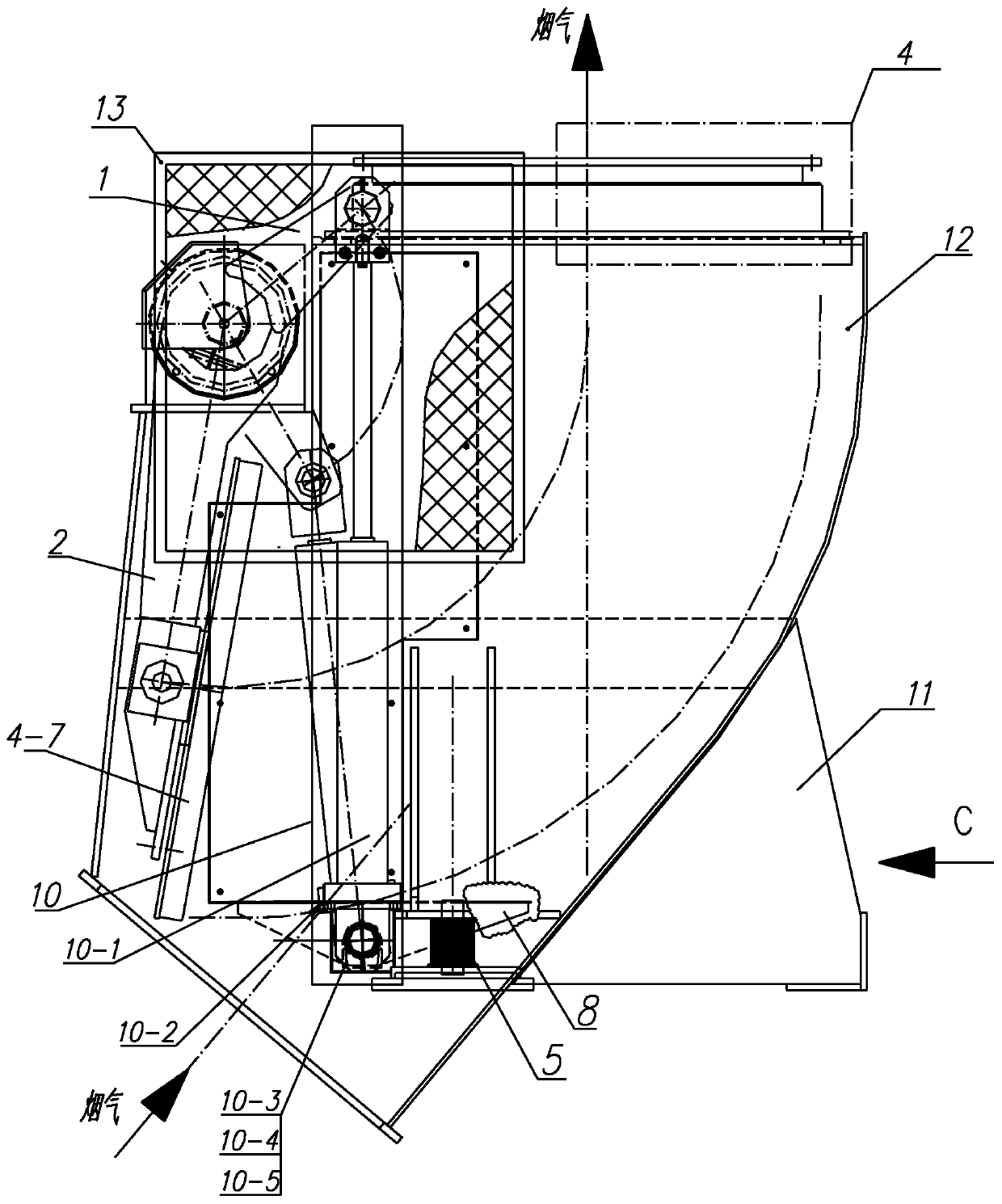
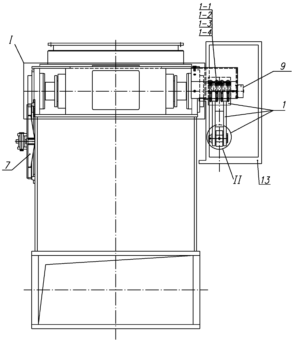
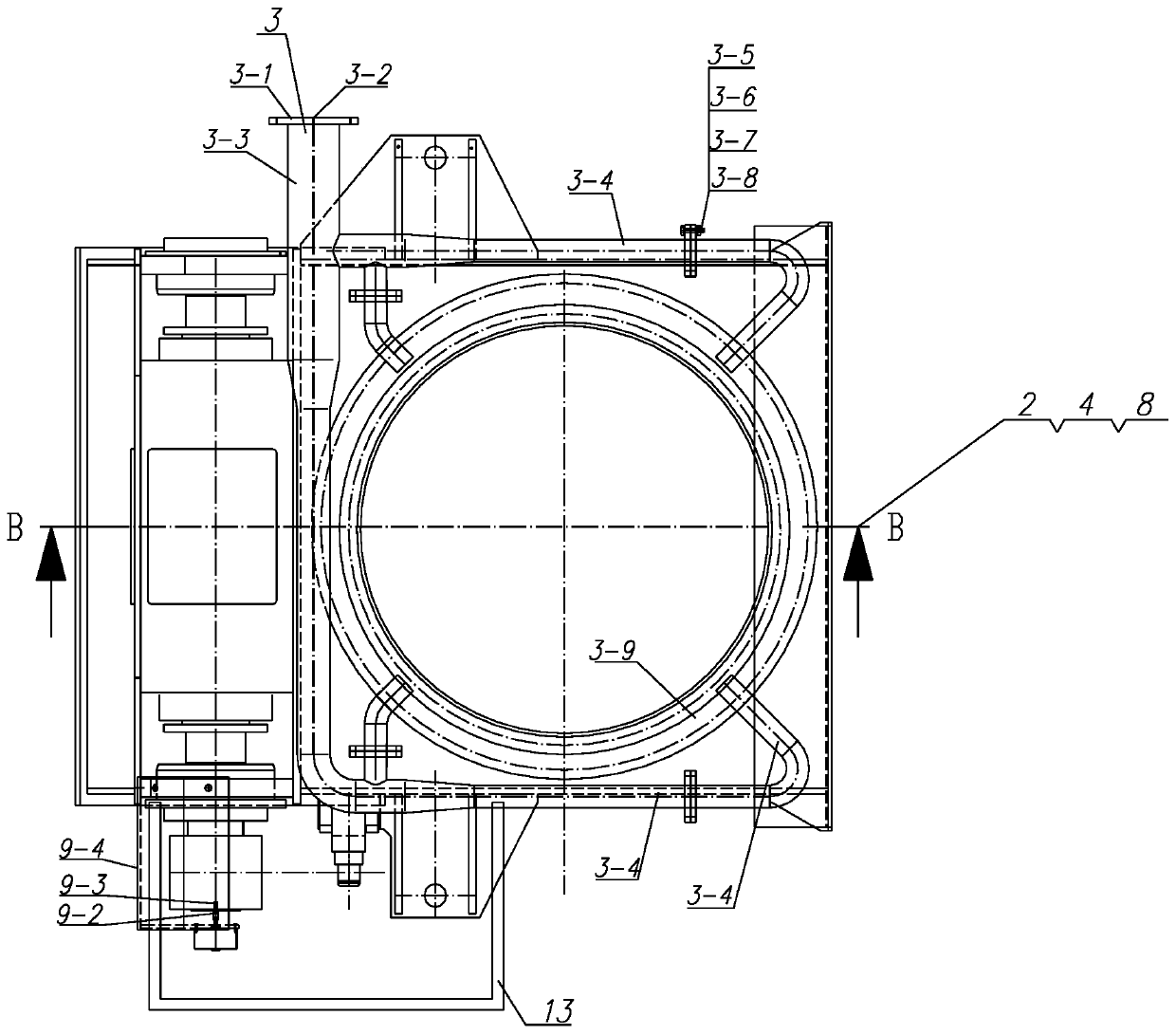
[0041] Such as Figure 1-Figure 3 As shown in the present invention, a large-scale high-temperature relief valve that can quickly replace the driving device includes a valve body, a valve plate 4-7, and a valve plate driving mechanism; one end of the valve body is provided with a smoke inlet, and the other end is provided with a smoke inlet. The gas outlet, the valve plate 4-7 is located in the valve body, the valve plate 4-7 can rotate under the drive of the valve plate driving mechanism, and close or open the flue gas outlet; the valve plate driving mechanism is controlled by a two-way buffer driving device 10 , transmission shaft 6-16, drive arm 1 and connecting arm 2; The other end of 1 passes through opening elastic axle hub 1-5 (as Figure 4 shown) is connected to the transmission shaft 6-16, and the opening of the open elastic hub 1-5 is ...


PUM


Abstract

The invention relates to a large high-temperature releasing valve capable of rapidly replacing a drive device. A valve body, a valve plate and a valve plate drive mechanism are included. The valve plate drive mechanism is composed of a both-way buffering drive device, a transmission shaft, a drive arm and a connection arm. A push rod of the both-way buffering drive device is hinged to one end of the drive arm, and the other end of the drive arm is connected with the transmission shaft through an opening elastic shaft hub. One end of the connection arm is connected with the transmission shaft through a split shaft hub, and the connection arm is fixedly connected with one half shaft hub. The other end of the connection arm is connected with the valve plate. Under driving of the both-way buffering drive device, the drive arm drives the transmission shaft to rotate, and then the connection arm and the valve plate are driven to integrally rotate. The large high-temperature releasing valve can achieve integral rapid replacement of the transmission shaft, the connection arm and the valve plate, the service life of a transmission shaft bearing and a valve port rubber seal ring can be further prolonged, the valve plate rotation position precision is improved, and safety of operation personnel is guaranteed.

Description

technical field [0001] The invention relates to the technical field of high-temperature valves, in particular to a large-scale high-temperature release valve capable of rapidly replacing a driving device. Background technique [0002] In case of emergency, the smoke and dust release system of the lime shaft kiln needs to close the main valve on the dust removal pipeline, open the smoke release valve on the smoke and dust pipeline, and release the smoke and dust in the kiln chamber; It is used in the middle of the valve, and the sealing performance is relatively high when it is closed. During maintenance, maintenance personnel need to enter the valve to carry out operations, mainly to replace the bearings and sealing rubber parts regularly. [0003] At present, the structure of the commonly used flue gas release valve has the following defects: First, because the temperature of the flue gas in the kiln is relatively high (sometimes exceeding 200°C) and the amount of dust is r...

Claims


Application Information

Patent Timeline
Patent Type & Authority Applications(China)
IPC IPC(8): F16K1/20F16K1/36F16K1/46F16K27/02F16K31/44F16K49/00F16K1/32
CPCF16K1/20F16K1/2035F16K1/205F16K1/2085F16K1/32F16K1/36F16K1/46F16K27/0227F16K31/44F16K49/00
Inventor 夏敬山潘中伟杨耕桃
Owner ACRE COKING & REFRACTORY ENG CONSULTING CORP DALIAN MCC
Why Eureka
Try Eureka