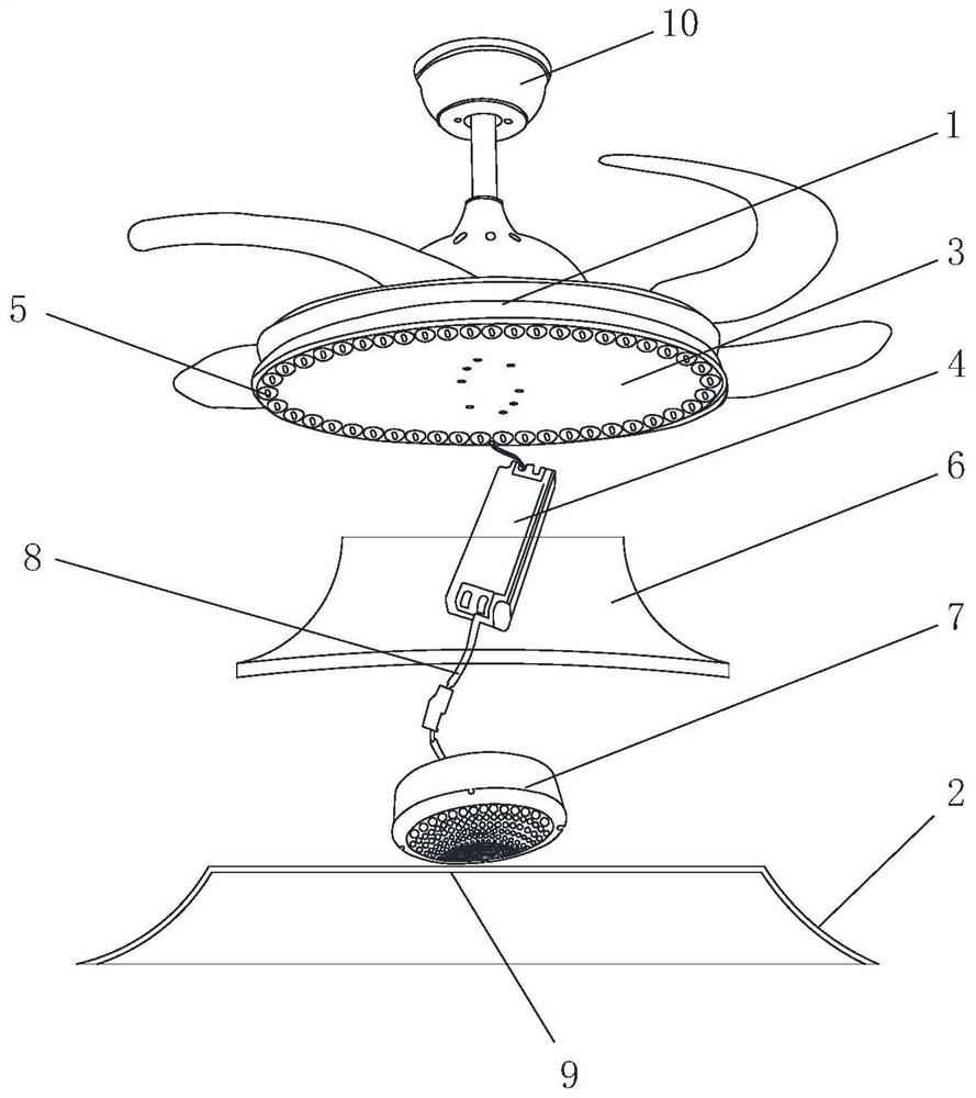
A heating fan lamp

A fan lamp and heating technology, which is applied to the parts of lighting devices, lighting and heating equipment, fixed lighting devices, etc., can solve the problems that fan lights cannot effectively use space and blade structure, etc., to improve the heating range and improve the heating effect. , the effect of preventing dark spots

Active Publication Date: 2022-04-12
刘平
View PDF3 Cites 0 Cited by
  • Summary
  • Abstract
  • Description
  • Claims
  • Application Information

AI Technical Summary

Problems solved by technology

[0004] In order to overcome the various defects of the existing indoor heating methods and the problem that the fan lamp cannot effectively use its space and blade structure, the embodiment of the present invention provides a heating fan lamp, which includes a suspender, a housing and a The light source in the casing, the casing includes an upper casing and a lower casing, a fan assembly is provided on the top surface of the upper casing, a mounting surface is formed on the bottom surface of the upper casing, a driver is provided in the middle of the mounting surface, A light source is provided on the edge of the installation surface, and a translucent cover is formed at the bottom of the lower casing for the light of the light source to emit. connected, the heating device includes a front cover and a rear cover, the rear cover is provided with a power board and an air inlet, the front cover is provided with an air outlet, and an air duct is formed between the air inlet and the air outlet. The air duct between the front cover and the rear cover is also provided with a fan and a heating plate connected to the power board in sequence from top to bottom, and the front cover is also provided with a shunt cover at the bottom of the air outlet

Method used


Image

  • A heating fan lamp
  • A heating fan lamp

Examples


Embodiment Construction

[0016] In order to make the technical problems, technical solutions and beneficial effects solved by the present invention clearer, the present invention will be further described in detail below in conjunction with the accompanying drawings and embodiments. It should be understood that the specific embodiments described here are only used to explain the present invention, not to limit the present invention.

[0017] When ordinal numerals such as "first" and "second" (if any) are mentioned in the embodiments of the present invention, it should be understood that they are only used for distinction unless they really express the order according to the context.

[0018] In the description of the present invention, it should be noted that, unless otherwise specified and limited, the terms "installation", "connection" and "connection" (if any) should be interpreted in a broad sense, for example, it may be a fixed connection, or It can be a detachable connection or an integral conne...


PUM


Abstract

The invention discloses a heating fan lamp, comprising a boom, a casing and a light source arranged in the casing, the casing includes an upper casing and a lower casing, and a fan assembly is arranged on the top surface of the upper casing , a mounting surface is formed on the bottom surface of the upper shell, a driver is provided in the middle of the mounting surface, a light source is provided on the edge of the mounting surface, and a light-transmitting cover is formed at the bottom of the lower shell for the light of the light source to be emitted, A heating device is arranged in the lower middle part of the lower casing, and the driver is connected to the heating device through wires. The heating device includes a front cover and a rear cover. The rear cover is provided with a power board and an air inlet. The hood is provided with an air outlet, and an air duct is formed between the air inlet and the air outlet, and the air duct between the front hood and the rear hood is also sequentially provided with a fan and a heater connected to the power board from top to bottom. The front cover is also provided with a diverter cover at the bottom of the air outlet. The integrated design of the embodiment of the present invention has a good application prospect.

Description

technical field [0001] The invention relates to the lighting field, in particular to a heating fan lamp. Background technique [0002] In winter, due to the relatively cold weather, heat dissipation oil heaters, small suns, air conditioners, Yuba or heaters are usually used for heating indoors. Among them, heat dissipation oil heaters and small suns need to occupy the ground, which affects the daily activities of users, while Yuba and heaters need to be specially buried. It is inconvenient to install the cable and lay the suspended ceiling. Although the air conditioner realizes the integration of cooling and heating, the price of the heating and cooling air conditioner is higher than that of the single cooling air conditioner, so it is not easy to popularize. [0003] Existing lamps, such as fan lamps, usually provide lighting for users and also have the function of a fan. On the one hand, the fan lamp is used to create a diffuse light and shadow effect, and on the other han...

Claims


Application Information

Patent Timeline
Patent Type & Authority Patents(China)
IPC IPC(8): F21S8/06F21V33/00F04D25/08F24H3/04F24H9/1863
CPCF21S8/063F21V33/0092F21V33/0096F04D25/088F24H3/0411F24H9/1863
Inventor 刘平
Owner 刘平
Why Eureka
Try Eureka