Moving device for oxygen lance and industrial furnace with moving device

A technology of mobile devices and oxygen lances, which is applied in hoisting devices, hoisting devices, furnaces, etc., can solve the problems of narrow heating range, difficulty in ensuring accuracy, and small speed regulation range, and achieve the effect of expanding the heating range

Pending Publication Date: 2017-08-18
SHENWU TECH GRP CO LTD
View PDF0 Cites 3 Cited by
  • Summary
  • Abstract
  • Description
  • Claims
  • Application Information

AI Technical Summary

Problems solved by technology

In the related technology, the oxygen lance is only heated by spraying oxygen at a fixed point. There is a lifting action to spray oxygen on the liquid surface or in the liquid,

Method used


Image

  • Moving device for oxygen lance and industrial furnace with moving device
  • Moving device for oxygen lance and industrial furnace with moving device
  • Moving device for oxygen lance and industrial furnace with moving device

Examples


Embodiment 1

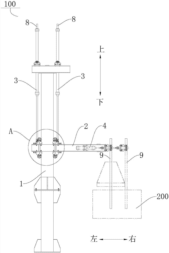
[0056] Such as figure 1 As shown, the moving device 100 for the oxygen lance 9 according to the embodiment of the present invention includes: a column 1 , a beam 2 , a vertical drive mechanism, a horizontal drive mechanism and a guide wheel set 5 .

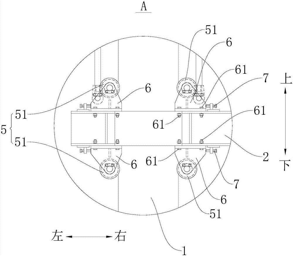
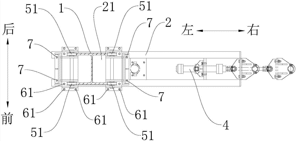
[0057] Specifically, as figure 1 and image 3 As shown, the column 1 is I-shaped steel, the flange of the column 1 is formed as a slideway, the slideway extends along the vertical direction of the column 1, the left end of the beam 2 is provided with a through hole 21 that penetrates up and down, and the column 1 is penetrated through the through hole 21 Inside, the right end of the crossbeam 2 is located on the right side of the slideway, which is close to the industrial furnace 200 and directly above the furnace mouth of the industrial furnace 200 . The vertical driving mechanism is arranged on the column 1, the vertical driving mechanism is connected with the beam 2 to drive the beam 2 to move along the slideway, the horizont...

Embodiment 2

[0065] Such as Figure 5 As shown, the structure of this embodiment is substantially the same as that of Embodiment 1, wherein the same components use the same reference numerals, the only difference is that there is one vertical hydraulic cylinder 3, and the mobile device 100 also includes a counterweight 12, The upper end of column 1 is provided with guide pulley 11, and the upper end of counterweight 12 is connected with steel wire rope, and steel wire rope walks around guide pulley 11 and is connected with beam 2. Thereby, the driving force of the vertical driving mechanism can be reduced.

[0066] The industrial furnace 200 according to the embodiment of the present invention includes the above-mentioned moving device 100 for the oxygen lance 9 . The beam 2 is located on one side of the column 1 which is close to the industrial furnace 200 . The beam 2 is directly above the furnace mouth of the industrial furnace 200 .

[0067] According to the industrial furnace 200 o...


PUM


Abstract

The invention discloses a moving device for an oxygen lance and an industrial furnace with the same, wherein the moving device includes: a column, the flange of which is formed as a slideway, and the slideway extends along the length direction of the column; On the column, the beam is perpendicular to the column, and the beam is located on one side of the column; the vertical drive mechanism, the vertical drive mechanism is arranged on the column, and the vertical drive mechanism is connected with the beam to drive the beam to move along the slideway; and the horizontal drive mechanism, the horizontal drive mechanism is set On the beam, the horizontal drive mechanism is connected with the oxygen lance to drive the oxygen lance to move. According to the moving device of the present invention, by setting the vertical drive mechanism to drive the crossbeam to move up and down, and setting the horizontal drive mechanism to drive the oxygen lance to move horizontally and horizontally, both the up and down movement of the oxygen lance and the lateral movement of the oxygen lance can be realized, so that the oxygen lance can be moved The heating of multiple areas expands the heating range of the oxygen lance.

Description

technical field [0001] The invention relates to the technical field of lifting devices, in particular to a moving device for an oxygen lance and an industrial furnace with the same. Background technique [0002] Oxygen lance lifting device is a kind of equipment that can realize automatic control in metallurgy and foundry industry, and is widely used in smelting, foundry, chemical industry and other industries. In the related technology, the oxygen lance is only heated by spraying oxygen at a fixed point, and has a lifting action to spray oxygen on the liquid surface or in the liquid, and the heating range is narrow. In addition, the structure of the lifting device is complicated, the accuracy is difficult to guarantee, and the speed regulation range is small. Contents of the invention [0003] The present invention aims to solve at least one of the technical problems existing in the prior art. For this reason, the present invention proposes a moving device for an oxygen ...

Claims


Application Information

Patent Timeline
IPC IPC(8): F27D3/16B66F19/00
CPCF27D3/16B66F19/00F27D2003/164
Inventor 吴钰锋余幼民吴道洪
Owner SHENWU TECH GRP CO LTD
Why Eureka
Try Eureka