Supercharge Your Innovation With Domain-Expert AI Agents!

Multi-line ground-contacting demarcation device

The technology of a line throwing instrument and instrument is applied in the field of positioning laser tools for building interior decoration and construction, which can solve the problems that the instrument is difficult to find the center accurately, cannot conveniently mark the function, and is time-consuming and labor-intensive, and achieves the effect of eliminating the influence of the positioning effect

Inactive Publication Date: 2020-07-28
南通品王机电有限公司
View PDF0 Cites 0 Cited by
  • Summary
  • Abstract
  • Description
  • Claims
  • Application Information

AI Technical Summary

Problems solved by technology

[0002] Most of the existing laser marking line casting instruments have a core component and a core base component. The core component includes an outer ring, an inner ring, a bearing, a shaft sleeve, a pressure ring and a pendulum. The group is located in the middle of the instrument, and the horizontal laser line expansion angle of the emission is about 110°. The emission angle is small, and it is far from the ground, which is inconvenient to use in floor construction.
[0003] As we all know, when laying tiles on the ground or walls, a pull rope or a hanging hammer is needed as a reference. This traditional construction method is time-consuming and laborious, and the position of the pull rope on the working surface also affects the construction operation; while the existing laser marking type casting line Due to the limitation of laser emission angle and assembly structure of the laser transmitter itself, it is also difficult to project a reference laser line close to the ground or wall, so that it cannot conveniently play a marking role
[0004] The floor and wall line throwing instruments in the existing market do not have the upper and lower laser reference points, so it is difficult for the instrument to accurately find the center during the stakeout process.

Method used


Image

  • Multi-line ground-contacting demarcation device
  • Multi-line ground-contacting demarcation device
  • Multi-line ground-contacting demarcation device

Examples


Embodiment Construction

[0017] In order to make the object, technical solution and advantages of the present invention clearer, the present invention will be further described in detail below through the description of the drawings and specific implementation examples.

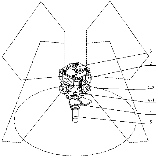
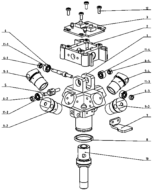
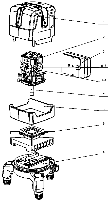
[0018] A multi-line sticking line throwing instrument, such as figure 1 As shown, the lower laser module-3 forming the horizontal positioning surface and the lower point is provided, and four vertical laser modules 4-1, 4-2, 4-3, which are perpendicular to the horizontal positioning surface and are orthogonal to each other, 4-4. The beam emitted by the lower laser head is located at the bottom of the multi-line ground-attached line projection instrument, and the laser beam forms a 360° positioning plane between the main body of the ground wall instrument and the ground. The mechanism can also be installed with a top laser head, the top laser module is installed on the pendulum above the cross shaft, and the top of the pendulum body c...


PUM


Abstract

The invention discloses a multi-line ground-contacting demarcation device. The internal structure of the core of the demarcation device is changed; a lower laser head for 360-degree demarcation is adopted; the lower laser head emits a light beam at 360 degrees to be positioned at the bottom end of the ground-contacting demarcation device; the lower laser head can emit a lower alignment point whichis perpendicular to the ground at the same time; and therefore, a laser beam surface is positioned between a ground-contacting demarcation main body and the ground. The multi-line ground-contacting demarcation device is provided with base shafting capable of rotating by 360 degrees; the instrument is provided with four vertical lines passing through the zenith; a cross intersection is formed at the top of the instrument; and when the base shafting is rotated by 360 degrees, the cross intersection of the zenith is coaxial with the lower alignment point and the shafting and is perpendicular tothe ground. The internal structural design of the multi-line ground-contacting demarcation device is changed, so that the arrangement position of the laser head can be adjusted, so that the problem that a laser positioning device cannot be effectively close to the ground and a ceiling surface is solved, and the influence of the size of laser on a positioning effect is eliminated.

Description

technical field [0001] The invention belongs to the field of positioning laser tools for building interior decoration and construction, in particular to a laser-assisted ceiling, wall and ground positioning device. Background technique [0002] Most of the existing laser marking line casting instruments have a core component and a core base component. The core component includes an outer ring, an inner ring, a bearing, a shaft sleeve, a pressure ring and a pendulum. The group is located in the middle of the instrument, and the emitted horizontal laser line expands at an angle of about 110°. The emission angle is small, and it is far away from the ground, which is inconvenient to use in floor construction. [0003] As we all know, when laying tiles on the ground or walls, a pull rope or a hanging hammer is needed as a reference. This traditional construction method is time-consuming and laborious, and the position of the pull rope on the working surface also affects the const...

Claims


Application Information

Patent Timeline
IPC IPC(8): G01C15/00
CPCG01C15/004
Inventor 潘金辉
Owner 南通品王机电有限公司
Features
  • R&D
  • Intellectual Property
  • Life Sciences
  • Materials
  • Tech Scout
  • Unparalleled Data Quality
  • Higher Quality Content
  • 60% Fewer Hallucinations
Learn More