
Power electronic converter fault diagnosis method and diagnosis system

A converter failure, power electronics technology, applied in the direction of instruments, character and pattern recognition, computer components, etc., can solve the problems of unreliable fault diagnosis rate and increase the uncertainty of fault information, so as to make up for unreliability and Uncertainty, effect of reducing disturbance

Pending Publication Date: 2020-07-28
FUZHOU UNIV
View PDF2 Cites 3 Cited by
  • Summary
  • Abstract
  • Description
  • Claims
  • Application Information

AI Technical Summary

Problems solved by technology

Although the traditional method can also be used to diagnose faults, due to the interference of other factors such as noise in the collected single fault information, the uncertainty of the collected fault information is increased, and the fault diagnosis rate is often not reliable.

Method used


Image

  • Power electronic converter fault diagnosis method and diagnosis system
  • Power electronic converter fault diagnosis method and diagnosis system
  • Power electronic converter fault diagnosis method and diagnosis system

Examples


Embodiment 1

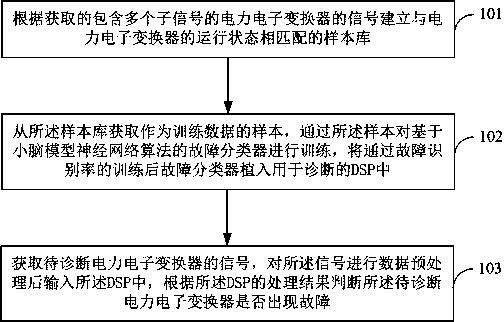
[0044] Such as figure 1 Shown is a flowchart of a power electronic converter fault diagnosis method provided by an embodiment of the present invention, and the diagnosis method includes:

[0045] In step S101, a sample library matching the operating state of the power electronic converter is established according to the acquired signal of the power electronic converter including a plurality of sub-signals.

[0046] In the embodiment of the present invention, the signal when the power electronic converter is running in a fault state is obtained from the power electronic converter, and after the signal is preprocessed, a sample library matching the operating state of the power electronic converter is established. Wherein, the signal of the power electronic converter includes but not limited to: sound signal, vibration signal, temperature signal.

[0047] The establishment of a sample library matching the operating state of the power electronic converter based on the acquired si...

Embodiment 2

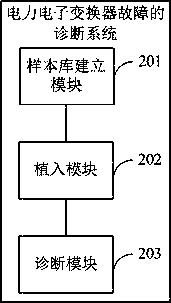
[0075] Such as figure 2 Shown is a structural diagram of a power electronic converter fault diagnosis system provided by an embodiment of the present invention, including:

[0076] The sample library building module 201 is configured to create a sample library matching the operating state of the power electronic converter according to the acquired signal of the power electronic converter including multiple sub-signals.

[0077] In the embodiment of the present invention, the signal when the power electronic converter is running in a fault state is obtained from the power electronic converter, and after the signal is processed, a sample library matching the running state of the power electronic converter is established. Wherein, the signal of the power electronic converter includes but not limited to: sound signal, vibration signal, temperature signal.

[0078] The establishment of a sample library matching the operating state of the power electronic converter based on the ac...


PUM


Abstract

The invention provides a power electronic converter fault diagnosis method and diagnosis system. The method comprises the following steps: establishing a sample library matched with the running stateof the power electronic converter according to an obtained signal of the power electronic converter containing a plurality of sub-signals; obtaining samples serving as training data from the sample library, training a fault classifier based on a cerebellum model neural network algorithm through the samples, and implanting the trained fault classifier passing the fault recognition rate into a DSP for diagnosis; and acquiring a signal of a to-be-diagnosed power electronic converter, performing data preprocessing on the signal, inputting the signal into the DSP, and judging whether the to-be-diagnosed power electronic converter has a fault or not according to a processing result of the DSP. According to the method, the interference of other factors such as noise on single state information iseffectively reduced, and the defects of unreliability and uncertainty of single fault sample information used in a traditional method are overcome.

Description

technical field [0001] The present application belongs to the field of power electronics, and in particular relates to a fault diagnosis method and a diagnosis system of a power electronic converter. Background technique [0002] As the main device of power electronic AC-DC conversion, the power electronic converter plays an important role in the process of ensuring high-efficiency conversion of electric energy transmission. Once the power electronic converter fails during operation, it will seriously endanger the stability and reliability of the entire system. Therefore, the application of fault diagnosis technology to power electronic converters is of great significance for the stable operation of power systems to realize rapid diagnosis of faulty equipment when faults occur. [0003] The traditional power electronic converter fault diagnosis method is to collect a single state information of the converter, and extract the fault characteristics of the single information f...

Claims


Application Information

Patent Timeline
Patent Type & Authority Applications(China)
IPC IPC(8): G06K9/00G06K9/62
CPCG06F2218/08G06F2218/12G06F18/2135G06F18/2414
Inventor 林琼斌韩子鹏陈四维王武黄捷
Owner FUZHOU UNIV
Learn More