Photovoltaic system for exterior walls of buildings

A photovoltaic system and building exterior wall technology, applied in the field of photovoltaic systems, can solve problems such as impact, large daily power consumption, affecting the normal operation of the entire building, etc., to reduce damage, solve building power consumption, and facilitate heat dissipation.

Active Publication Date: 2022-03-18
深圳信誉建设集团有限公司
View PDF10 Cites 0 Cited by
  • Summary
  • Abstract
  • Description
  • Claims
  • Application Information

AI Technical Summary

Problems solved by technology

[0003] At present, there are generally many high-rise buildings in cities, and the daily power consumption of the entire building is generally quite large. If the weather is bad or a temporary power outage occurs, it will affect the normal operation of the entire building, especially the indoor lighting and lighting. Lighting, will also be greatly affected, which needs to be improved urgently

Method used


Image

  • Photovoltaic system for exterior walls of buildings
  • Photovoltaic system for exterior walls of buildings
  • Photovoltaic system for exterior walls of buildings

Examples


Embodiment 1

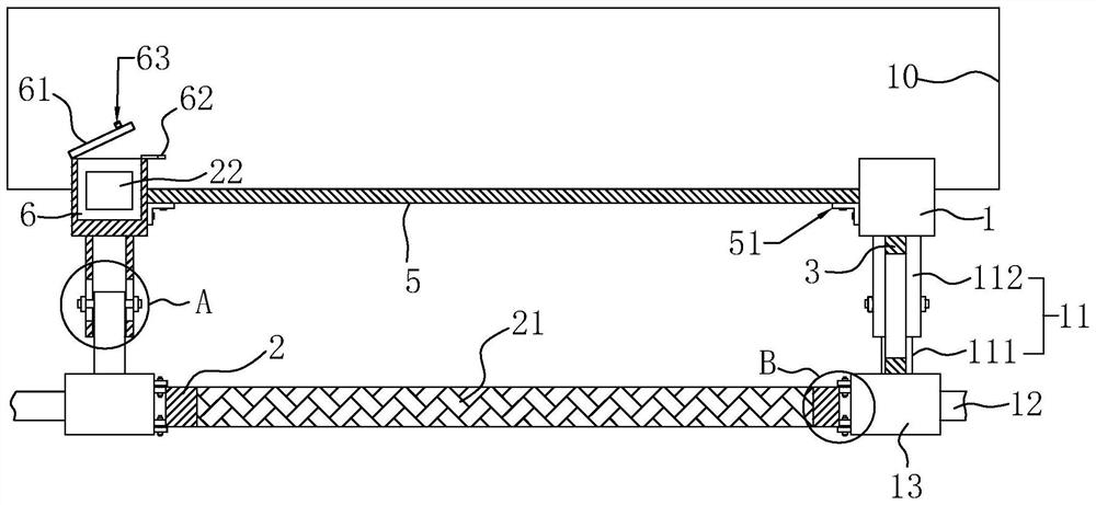
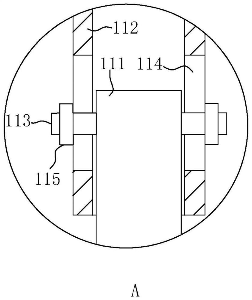
[0036] Embodiment 1: A kind of photovoltaic system of exterior wall of building, such as figure 1 and figure 2 As shown, there are multiple groups of columns 1 installed on the outer edge of the building body 10, and each group of columns 1 is two symmetrical, and a connecting column 11 is installed on the columns 1 in each group, and one end of the connecting column 11 is connected to the column. 1 phase is fixed, the other end extends out of the edge of the building body 10, and alloy beams 12 are fixed between the connecting columns 11, and fixed columns 13 are fixed on both ends of the alloy beams 12, the number of fixed columns 13 is the same as that of the columns 1 are consistent and parallel to each other.

[0037] A photovoltaic panel frame 2 is detachably installed between the fixing columns 13, a photovoltaic panel 21 is installed on the photovoltaic panel frame 2, the photovoltaic panel 21 is electrically connected to a battery 22, and a fixing member is also arr...

Embodiment 2

[0048] Embodiment 2: as Figure 5 As shown, the difference from Embodiment 1 lies in the difference of the heat dissipation device. In this embodiment, the heat dissipation device includes: a transparent plate 4 installed between the column 1 and the fixed column 13; and the exhaust fan 42 installed in the vent 41.

[0049] The setting of the transparent plate 4 can play a good lighting effect. When heat dissipation is required, the exhaust fan 42 can be turned on, so that the exhaust fan 42 on one side can discharge the hot air between the transparent plates 4 to the outside, while the exhaust fan 42 on the other side can discharge the hot air between the transparent plates 4 to the outside. The exhaust fan 42 can draw the outside air into the room, so as to realize the gas circulation very conveniently and effectively dissipate the heat generated by the photovoltaic module.

Embodiment 3

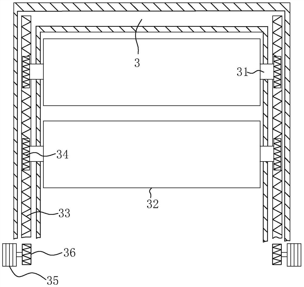
[0050] Embodiment 3: as Figure 6 As shown, the difference from other embodiments lies in the difference of the driver. In this embodiment, the driver includes: a cylinder 38 installed on the outside of the mounting frame 3; The stay wire 37 connected to the rack 33 passes through the mounting frame 3 .

[0051] When the cylinder 38 is opened, the piston rod of the cylinder 38 can drive the rack 33 to move up and down along the inner wall of the installation frame 3 through the backguy 37. Through this scheme, the rack 33 can be driven up and down to make the rotating plate 32 rotate.


PUM


Abstract

The invention relates to a photovoltaic system for building exterior walls, which belongs to the technical field of building exterior wall construction. The key points of the technical scheme include multiple sets of columns installed at the edge of the building; one end is fixed to the columns, and the other end extends out of the building. Connecting columns; alloy beams connected between the connecting columns; and multiple sets of fixing columns fixed on the alloy beams parallel to the columns, photovoltaic panel frames are detachably installed between the fixing columns, and the photovoltaic panel frames Installed inside is used to convert solar energy into electric energy for storage in photovoltaic modules, a connection assembly for connecting the two is provided between the fixed column and the photovoltaic panel frame, and a heat dissipation device for heat dissipation is also provided between the fixed column and the upright column device. When in use, the photovoltaic system of the present invention can convert solar energy into electric energy, effectively solve the electricity consumption situation of the building, reduce the influence of the building in the event of a power outage, and thus ensure the normal operation of the building.

Description

technical field [0001] The invention relates to the technical field of building exterior wall construction, in particular to a photovoltaic system for building exterior walls. Background technique [0002] In the process of building construction, it is often seen that glass curtain walls are installed on the exterior walls of buildings. The installation of glass curtain walls can enhance the lighting effect of the entire building, and at the same time, make the appearance of the building more beautiful. [0003] At present, there are generally many high-rise buildings in cities, and the daily power consumption of the entire building is generally quite large. If the weather is bad or a temporary power outage occurs, it will affect the normal operation of the entire building, especially the indoor lighting and lighting. Lighting, too, is greatly affected and needs to be improved. Contents of the invention [0004] In view of the deficiencies in the prior art, the purpose of...

Claims


Application Information

Patent Timeline
Patent Type & Authority Patents(China)
IPC IPC(8): H02J7/35H02S30/10H02S40/42
CPCH02S30/10H02S40/425Y02E10/50Y02B10/10
Inventor 李裕发李裕钊郑敏超李华忠
Owner 深圳信誉建设集团有限公司
Why Eureka
Try Eureka