Brake flange component

A technology for brake discs and components, applied in the field of brake disc components, can solve the problems of easy falling off of warning signs and difficult installation.

Active Publication Date: 2015-04-08
HONG ZHAN H P P SU ZHOUCO LTD
View PDF9 Cites 5 Cited by
  • Summary
  • Abstract
  • Description
  • Claims
  • Application Information

AI Technical Summary

Problems solved by technology

The warning signs installed on the brake disc are generally easy to fall off and difficult to install

Method used


Image

  • Brake flange component

Examples


Embodiment Construction

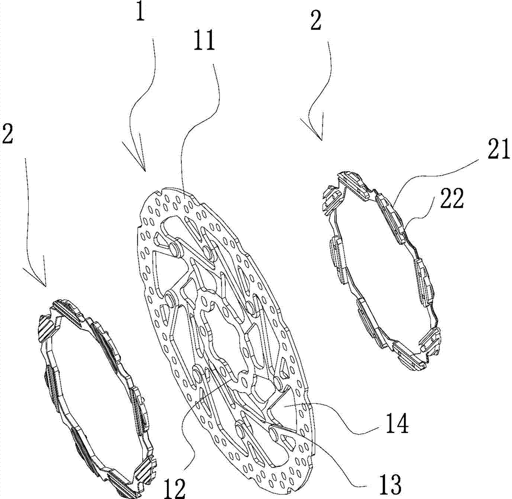
[0020] Such as figure 1 A brake disc assembly is shown, which includes a brake disc 1, and the brake disc 1 includes a brake part 11 located on the outer periphery, a mounting part 12 located on the inner periphery, and a brake part 11 and the mounting part located on the The transition portion 13 between 12 is installed on the heat dissipation ring 2 on both sides of the brake disc 1 for heat dissipation. The brake portion 11 of the brake disc 1 is provided with a plurality of through holes to increase the frictional force and heat dissipation effect of the brake portion 11 . In one embodiment, the transition portion 13 of the brake disc 1 is provided with a plurality of connecting holes 14 arranged in the circumferential direction, and the cooling ring 2 located on both sides of the brake disc 1 includes a plurality of connecting holes 14 arranged in the circumferential direction. The connecting portion 21 , the connecting portion 21 of the cooling ring 2 located on both...


PUM


Abstract

The invention discloses a brake flange component. The brake flange component comprises a brake flange; the brake flange comprises a brake part located on the periphery, an installing part located on the inner circumference, and a transition part located between the brake part and the installing part; and the brake flange component further comprises a heat radiating ring installed at two sides of the brake flange and used for radiating. The heat radiating ring is equipped with light sources, such as an LED, or is coated with fluorescent paint or reflectorized paint on the surface, is pasted with fluorescent label or reflectorized label, and is processed with other surface processing, such as anode processing and electroplating processing, for safety warning function; the heat radiating ring is opened with a wind guide channel, the brake flange is cooled by the wind formed in the driving process of the vehicles, the brake flange is not easily transformed, so the service life is prolonged; an inner ring is additionally equipped with an inertia generating device, or a solar generating device for satisfying the own requirements; the heat radiating ring is directly connected by male-female buttons for convenient detaching; and the heat radiating ring can be made as various shapes for decoration and beautification function.

Description

technical field [0001] The invention relates to a brake disc assembly. Background technique [0002] In the prior art, warning signs such as cooling rings are not installed on the brake disc. The warning signs installed on the brake discs are generally easy to fall off and difficult to install. Contents of the invention [0003] The technical problem to be solved by the present invention is to overcome the deficiencies of the prior art and provide a brake disc assembly. [0004] In order to solve the above technical problems, the present invention takes the following technical solutions: [0005] A brake disc assembly, which includes a brake disc, the brake disc includes a braking portion located on the outer periphery, a mounting portion located on the inner periphery, and a transition portion between the braking portion and the mounting portion, the The special brake disc assembly also includes heat dissipation rings installed on both sides of the brake disc for heat ...

Claims


Application Information

Patent Timeline
Patent Type & Authority Applications(China)
IPC IPC(8): F16D65/847
Inventor 谢维庭
Owner HONG ZHAN H P P SU ZHOUCO LTD
Why Eureka
Try Eureka