Galvanometer adjusting device, system and method and projector

A technology for adjusting devices and adjusting methods, which is applied in the field of projection display, can solve the problems of reducing user's visual experience, increasing projection image noise, projection quality interference, etc., and achieves the effect of improving visual enjoyment and image resolution

Inactive Publication Date: 2020-07-28
IVIEW DISPLAY SHENZHEN CO LTD
View PDF5 Cites 4 Cited by
  • Summary
  • Abstract
  • Description
  • Claims
  • Application Information

AI Technical Summary

Problems solved by technology

[0004] In the process of realizing the present invention, the inventors have found that there are at least the following problems in the above related technologies: the projection device that improves the resolution based on the vibration of the galvanometer will have the disadvantage of increasing the noise of the projected image, and when the projection output resolution is lower than or equal to the projection display When the image with the physical resolution of the chip is used, the vibrating lens cannot improve the resolution of the projected image very well. On the contrary, due to the increase of noise generated by the vibrating lens or the influence of image difference, it will interfere with the projection quality and reduce the user's vision. to feel

Method used


Image

  • Galvanometer adjusting device, system and method and projector
  • Galvanometer adjusting device, system and method and projector
  • Galvanometer adjusting device, system and method and projector

Examples


Embodiment 1

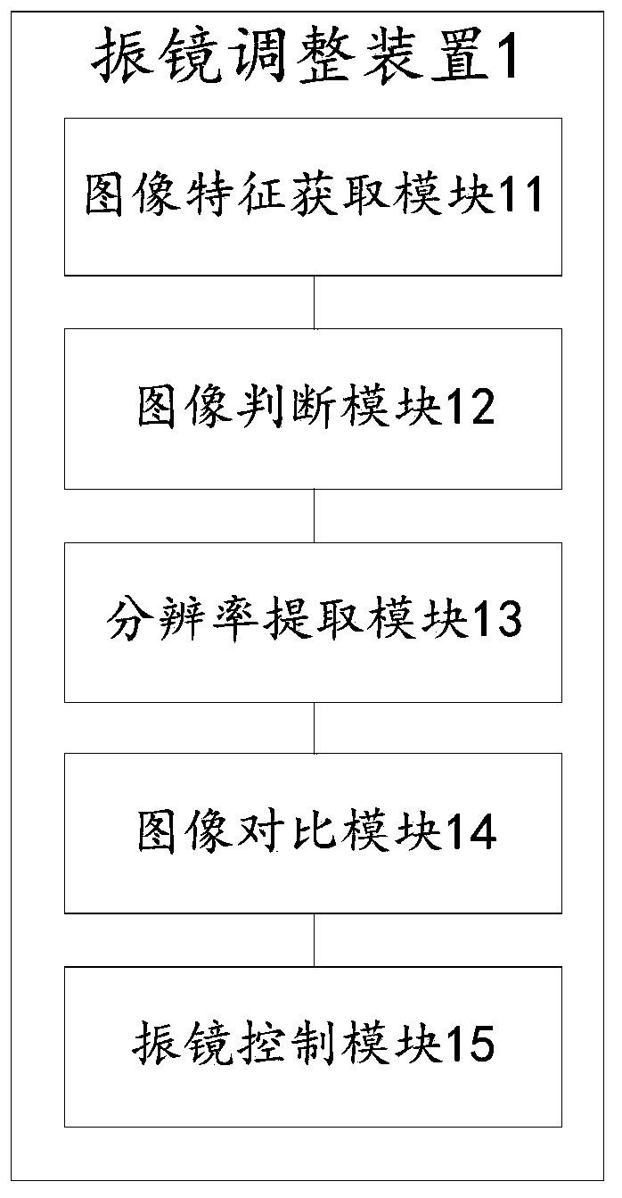
[0066] See figure 1 , figure 1 It is a schematic diagram of the overall structure of a galvanometer adjustment device 1 provided in Embodiment 1 of the present invention. In the embodiment of the present invention, a galvanometer adjustment device 1 is provided, including: an image feature acquisition module 11, an image judgment module 12, Resolution extraction module 13 , image comparison module 14 and galvanometer control module 15 , the galvanometer adjustment device 1 can adjust the state of the galvanometer switch according to the information characteristics of the projected image.

[0067] The galvanometer adjustment device 1 provided by the embodiment of the present invention can be applied to various projection equipment or projection devices that require improved projection resolution, for example, it can be a home projector or a projection device in a movie theater. It can also be some large-scale projection equipment projected on the air or on real objects. The a...

Embodiment 2

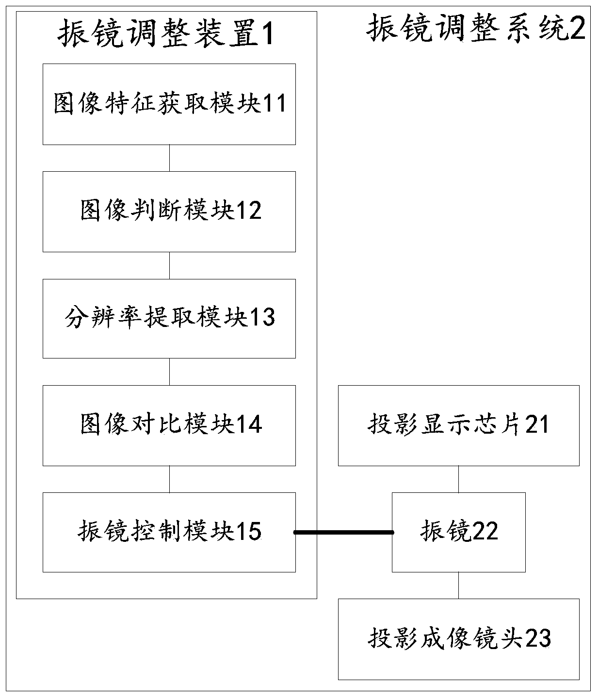
[0082] See figure 2 , figure 2 It is a schematic diagram of the overall structure of a vibrating mirror adjustment system 2 provided in the first embodiment of the present invention. In the embodiment of the present invention, a vibrating mirror adjustment system 2 is provided, including: the vibrating mirror described in the first embodiment above The adjusting device 1, and the vibrating mirror 22, the projection imaging lens 23 and the projection display chip 21, the vibrating mirror adjusting system 2 can adjust the switch state of the vibrating mirror 22 according to the information of the projected image.

[0083] The galvanometer adjustment system 2 provided by the embodiment of the present invention can be applied to a variety of projection equipment or projection devices that require improved projection resolution. For example, it can be a home projector or a projection device in a movie theater. It can also be some large-scale projection equipment projected on the...

Embodiment 3

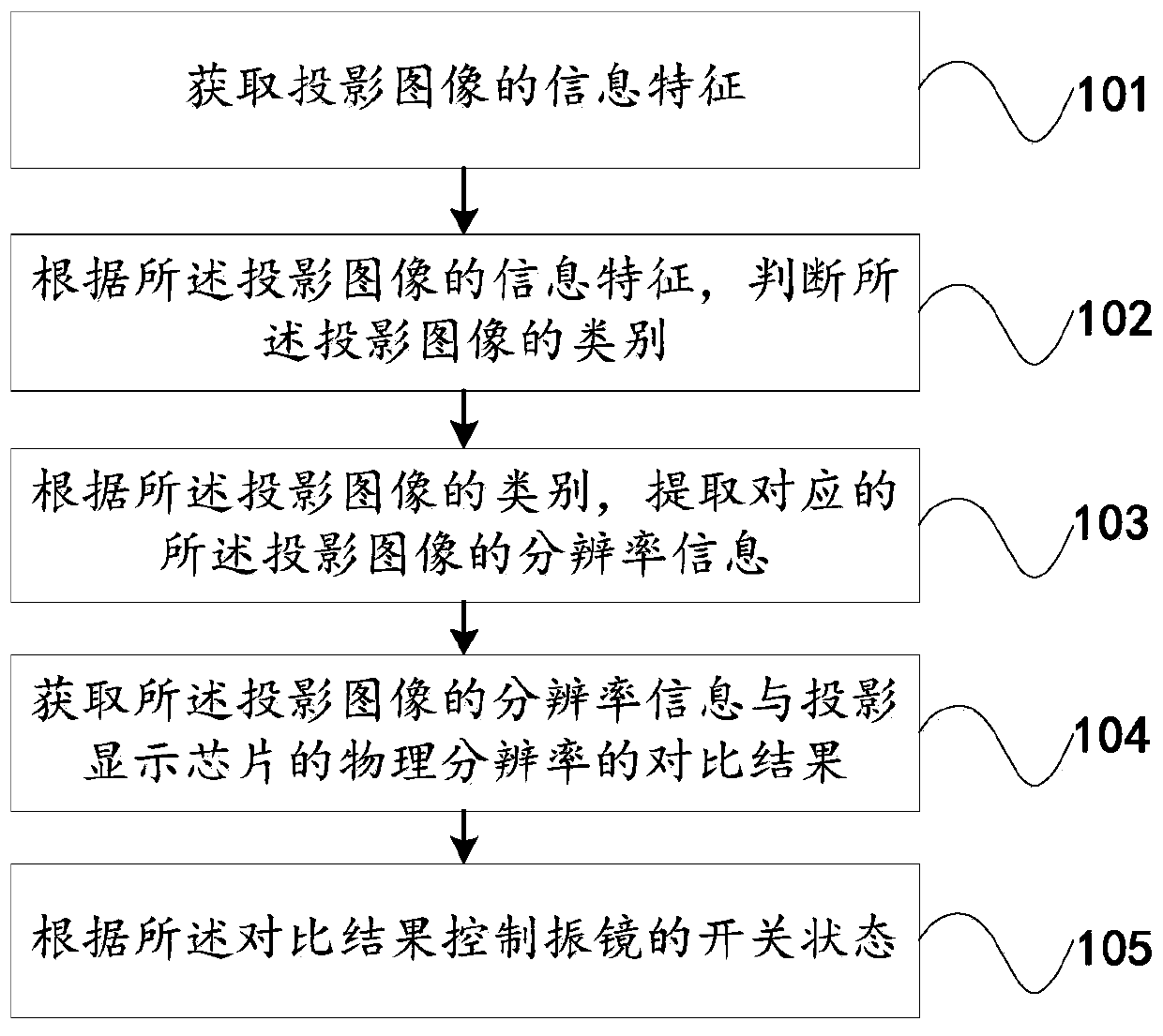
[0091] See image 3 , Figure 4 , Figure 5 , Figure 6 and Figure 7 , image 3 It is a schematic flow chart of a vibrating mirror adjustment method provided in Embodiment 3 of the present invention. In the embodiment of the present invention, a vibrating mirror adjustment method is provided. When other systems start up normally and start projection work, the galvanometer is adjusted through the galvanometer adjustment method, which includes but is not limited to the following steps:

[0092] Step 101: Obtain information features of the projected image.

[0093] In the embodiment of the present invention, it is necessary to read or decode the front-end information of the image, so as to obtain the information characteristics of the relevant image. The information characteristics of the image include but are not limited to: the output resolution of the static image, or The encoding method and resolution of the local dynamic image, or the playback resolution of the networ...


PUM


Abstract

The invention relates to a galvanometer adjusting device, a system and method and a projector in the technical field of projection display. The galvanometer adjusting device comprises an image featureacquisition module, an image judgment module, a resolution extraction module and a galvanometer control module. The galvanometer adjusting device judges the type of the projection image and the corresponding resolution information according to the acquired information characteristics of the projection image; therefore, whether the galvanometer needs to be started for vibration or not is judged toimprove the image resolution, the on-off state of the galvanometer is intelligently and automatically controlled correspondingly to achieve the optimal projection display effect, and the visual enjoyment of a user is greatly improved.

Description

technical field [0001] The invention relates to the technical field of projection display, in particular to a vibrating mirror adjustment device, system, method and projector. Background technique [0002] With the improvement of science and technology, projection imaging equipment is more and more widely used in people's work and life. The higher the resolution of projection imaging equipment, the higher the viewing experience of users. Image resolution is a major indicator of image quality, the higher the image resolution, the closer it is to the real scene. Improving image resolution is mainly through improving hardware equipment and image processing software. The way to improve hardware equipment is mainly to improve image imaging components and optical systems. [0003] In the prior art, vibrating mirrors (referred to as vibrating mirrors) are routinely used to improve resolution. Usually, the original single or combined key components in the optical system are improve...

Claims


Application Information

Patent Timeline
Patent Type & Authority Applications(China)
IPC IPC(8): H04N9/31
CPCH04N9/3188G06V10/42G03B21/28G02B7/182H04N9/3152
Inventor 高志强杨伟樑李勇杨承德林清云
Owner IVIEW DISPLAY SHENZHEN CO LTD
Why Eureka
Try Eureka