Remote temperature measurement system and method based on thermal imaging and face recognition

A technology of face recognition and thermal imaging, which is applied in the fields of character and pattern recognition, diagnostic recording/measurement, medical science, etc., can solve the problems of devices and methods that cannot accurately detect the temperature of the flow of people, and achieve high simultaneous measurement of the number of people. Simplify The Effect of Algorithmic Complexity

Pending Publication Date: 2020-07-31
成都电科慧安科技有限公司
View PDF0 Cites 5 Cited by
  • Summary
  • Abstract
  • Description
  • Claims
  • Application Information

AI Technical Summary

Problems solved by technology

However, there is no device and method in the prior art that can detect the temperature of the flow of peop

Method used


Image

  • Remote temperature measurement system and method based on thermal imaging and face recognition

Examples


Embodiment 1

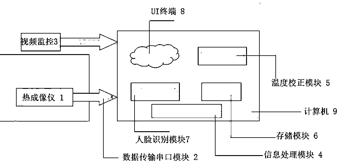
[0028] A remote temperature measurement system based on thermal imaging and face recognition, including thermal imager 1, data transmission serial port module 2, information processing module 4, temperature correction module 5, storage module 6, video monitoring 3, face recognition module 7. UI terminal 8; wherein: the information processing module 4, the temperature correction module 5, the storage module 6, the video surveillance 3, the face recognition module 7, the UI terminal 8 are installed in the computer 9 to run, the thermal imaging The instrument 1 is connected to the computer 9 through a data transmission serial port module 2 and the video surveillance 3 is connected to the computer 9 through a data transmission device.

[0029] The thermal imager 1 is used to collect temperature data of the target to be measured;

[0030] The data transmission serial port module 2 is used to transmit the temperature data collected by the thermal imager to the information processing modu...

Embodiment 2

[0044] Compared with embodiment 1, the difference of this embodiment is: the thermal imager 1 and the camera of the video surveillance 3 are installed together, so that the surveillance picture matches the thermal imaging display picture, and the thermal imaging and the surveillance video picture They are all displayed in the UI terminal 8 window, and their ranges are the same size and correspond to each other. Since both the thermal imager and the camera can be used to display the picture, the purpose of the simultaneous display of the two is to make the temperature in the camera video more intuitively displayed. Secondly, making the pictures overlap as much as possible can improve the accuracy in the subsequent monitoring picture segmentation program. The "installed together" means that the thermal imager can be installed around the camera close to the camera, and the two do not need to be directly connected.

[0045] Since the thermal imager and the video surveillance camera a...

Embodiment 3

[0047] Compared with Embodiment 2, the difference of this embodiment is that the system also includes a distance measuring probe, which is used to measure the distance between the target to be measured and the thermal imager, and the measurement is performed through the data serial port module. The distance data is sent to the data processing center for information processing and sent to the temperature correction module for temperature correction.

[0048] In the working step 2 of using the device for remote temperature measurement: the distance between the target to be measured and the thermal imager is measured with a ranging probe.


PUM


Abstract

The invention provides a remote temperature measurement system and method based on thermal imaging and face recognition. The system and method can achieve real-time, quick and precise detection of thepedestrian flow temperature in a large scene with large pedestrian flow and complex conditions. According to the device and method provided by the invention, a thermal imager is used for synchronously acquiring the body temperature of the human body in the large scene, a distance measuring probe is used for measuring the distance from an object to the sensor, a serial port module is used for transmitting data to an upper computer for information processing, temperature information of all positions in a monitoring range is obtained by combining with a temperature correction processing algorithm, all faces appearing in a picture are captured through a face recognition algorithm, and real-time temperature measurement is carried out on all the faces appearing in monitoring according to position coordinates of the faces in monitoring by combination with the known temperature information.

Description

Technical field [0001] The invention belongs to the field of human body temperature detection, and in particular relates to a temperature measurement system with a human-computer interaction interface through thermal imaging and face recognition, and a method for realizing large-scene, high-precision, and real-time temperature measurement. Background technique [0002] Nowadays, the method to realize the rapid detection of human body temperature mainly relies on infrared temperature sensors, which can realize the measurement of body temperature based on the infrared energy emitted by the human body. Currently widely used products are mainly forehead thermometers and fixed infrared thermometers placed at the gate of the gate, but both have certain defects. The former can only measure a single target at a time, which is inefficient and is not suitable for passenger flow dispersion. In large scenes, the latter analyzes the thermal imaging parameters of the shooting crowd. It is diff...

Claims


Application Information

Patent Timeline
IPC IPC(8): A61B5/01G06K9/00
CPCA61B5/01A61B5/743A61B5/7435A61B5/7264A61B5/746G06V40/172
Inventor 殷光强候少麒常益凡李超
Owner 成都电科慧安科技有限公司
Why Eureka
Try Eureka