Cable straightening device for communication engineering

A communication engineering and cable technology, which is applied in the field of cable straightening equipment, can solve the problems such as the large size of the cable straightening equipment, which is inapplicable and troublesome, and achieves the effect of small overall structure and easy use.

Inactive Publication Date: 2020-07-31
合肥智瑞工程科技有限公司
View PDF1 Cites 1 Cited by
  • Summary
  • Abstract
  • Description
  • Claims
  • Application Information

AI Technical Summary

Problems solved by technology

[0004] The purpose of the present invention is to provide a cable straightening device used in communication engineering. Through the setting of the locking mechanism, clamping mechanism, pressure sensor, etc., it solves the problem that the existing cable straightening device is too large to be suitable for Straightening during cable installation, manual straightening operation during cable installation is troublesome, and manual straightening cannot avoid the problem of over-stretching the cable

Method used


Image

  • Cable straightening device for communication engineering
  • Cable straightening device for communication engineering
  • Cable straightening device for communication engineering

Examples


Embodiment 1

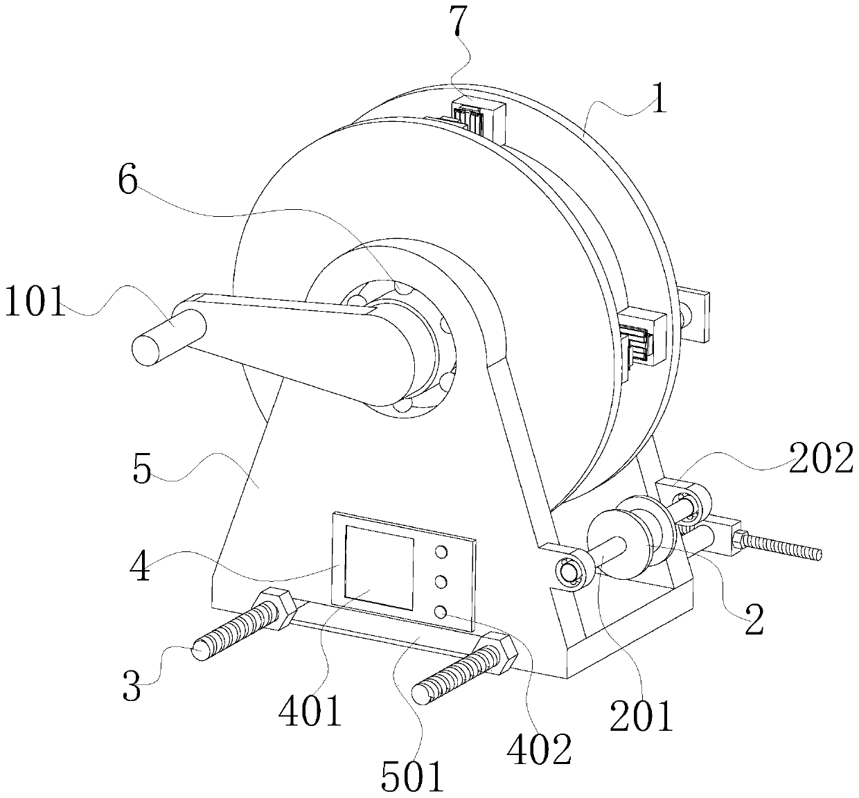
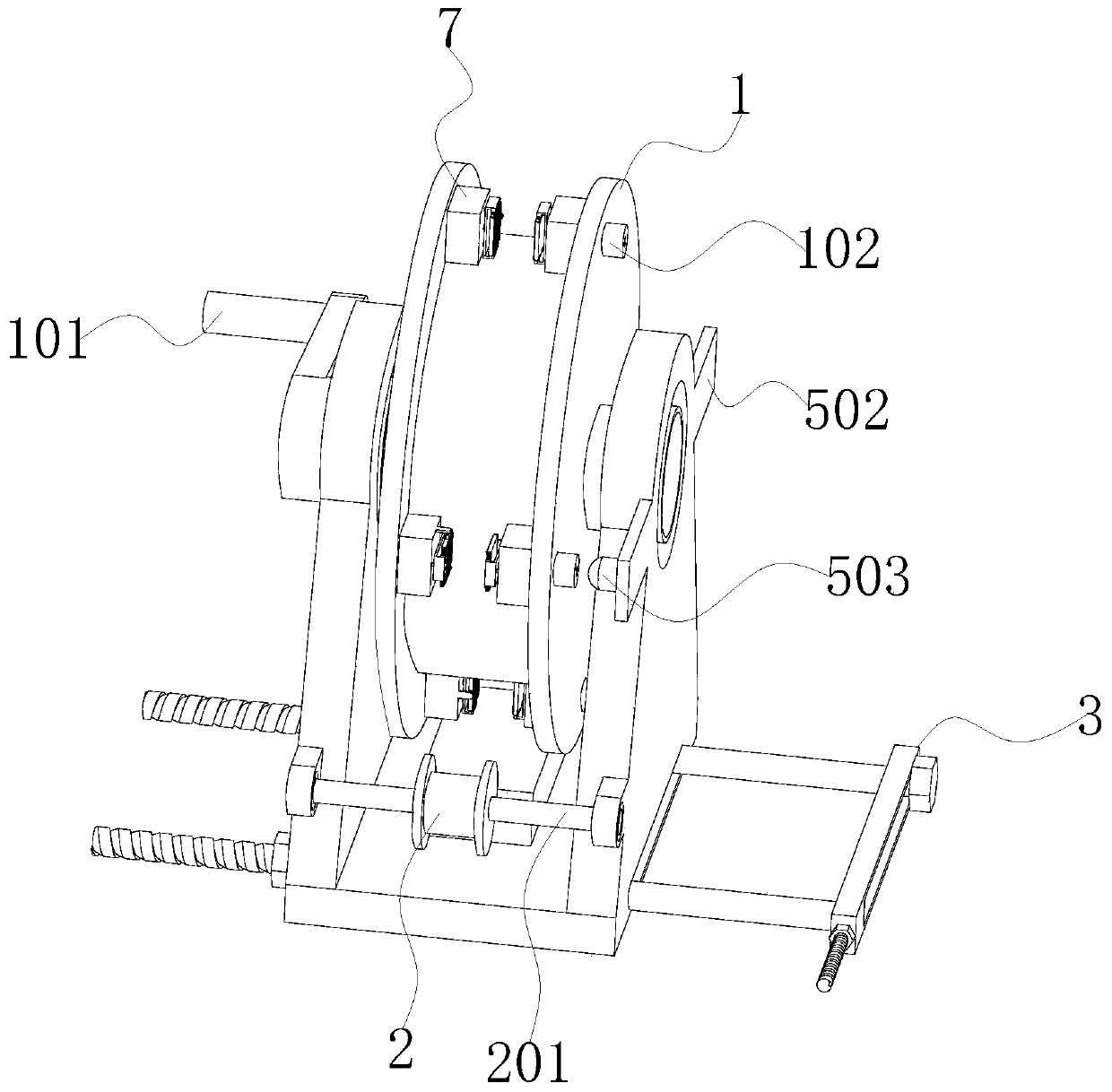
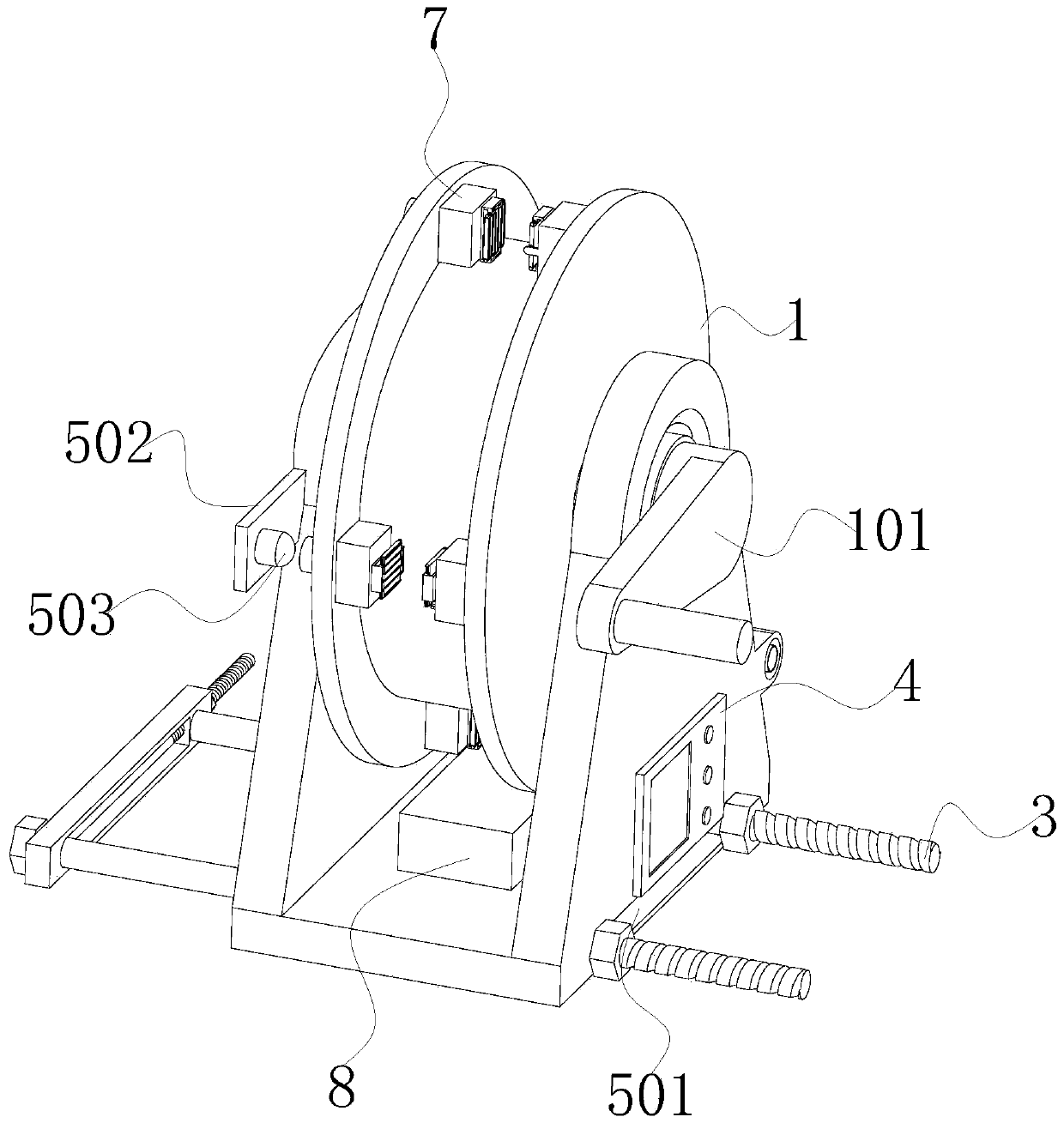
[0037] see Figure 1-5 As shown, the present invention is a cable straightening device used in communication engineering, including a rotating roller 1, a base 5 and a clamping mechanism 7, the inner upper end of the base 5 is provided with a rotating roller 1, and two rotating rollers 1 are opposite to each other. There are four groups of clamping mechanisms 7 uniformly distributed along the circumferential direction on the inner surface of the inner surface, and each group of clamping mechanisms 7 is composed of two opposite clamping mechanisms 7, and the two clamping mechanisms 7 in each group cooperate with each other. The cable can be clamped under;

[0038] The center position of the rotating roller 1 is fixedly fitted with a rotating shaft 103, and the two ends of the rotating shaft 103 are respectively connected to the base 5 through rolling bearings 6. The end of the rotating shaft 103 farther away from the infrared emitter 503 is fixedly connected with a rotating han...

Embodiment 2

[0059] Based on the heating assembly described in the first embodiment, the rotating roller 1 is covered with a rope, which can realize the use of the device from the upper end of the communication pole transported from the lower end of the communication pole.

[0060] In addition, in order to improve the fixing stability of the device, the friction coefficient between the device and the communication rod can be improved by setting the damping material pad on the opposite side of the limiting strip 302 described in the first embodiment and the base 5 .


PUM


Abstract

The invention discloses a cable straightening device for communication engineering, and relates to the technical field of communication engineering. The cable straightening device comprises a rotatingroller, a base and clamping mechanisms, wherein the rotating roller is arranged at the upper end position of the inner side of the base, the four sets of clamping mechanisms are uniformly distributedon the two opposite inner sides of the rotating roller in the circumferential direction, and each set of clamping mechanisms is composed of two opposite clamping mechanisms; a through limiting grooveis formed in a bottom plate of the base; mounting plates are symmetrically arranged at the two ends of the outer wall of one side of the base, and an infrared emitter is fixedly mounted on the outerwall of one side, close to the rotating roller, of each mounting plate; and the outer surface of one side, close to the infrared emitters, of the rotating roller is provided with four infrared receivers which correspond to the clamping mechanisms in a one-to-one mode in the circumferential direction. According to the cable straightening device, a cable is straightened in the cable installation process, so that the straightening efficiency is high; and according to the device, the cable stretching degree can be monitored in real time, so that excessive straightening is avoided.

Description

technical field [0001] The invention belongs to the technical field of communication engineering, and in particular relates to a cable straightening device used in communication engineering, which is mainly used for straightening the cable when the cable is installed. Background technique [0002] During the construction of communication projects, in order to improve the stability of cable installation, it is often necessary to straighten the cables during the installation of cables. At present, most of the existing cable straightening equipment are large in size and can only be used in Simply straighten the cable before installation, but it cannot be straightened during the cable installation process. Therefore, during the cable installation process, it is mainly stretched manually. This stretching method is cumbersome and inefficient to operate, and It is also difficult for the staff to grasp the stretching degree of the cable. If the stretching is excessive, the internal ...

Claims


Application Information

Patent Timeline
Patent Type & Authority Applications(China)
IPC IPC(8): B21F9/00H02G1/06
CPCB21F9/002H02G1/06
Inventor 雷振兴
Owner 合肥智瑞工程科技有限公司
Why Eureka
Try Eureka