Safe and efficient grooving machine

A slotting machine, high-efficiency technology, applied in the direction of sawing equipment, wood processing equipment, circular saws, etc., can solve the problems of unstable slotting quality, complicated slotting operation, low safety, etc., to reduce equipment purchase expenses, The effect of convenient and quick operation and high degree of automation

Pending Publication Date: 2020-07-31
厦门致尊科技有限公司
View PDF0 Cites 0 Cited by
  • Summary
  • Abstract
  • Description
  • Claims
  • Application Information

AI Technical Summary

Problems solved by technology

[0002] In the daily work of woodworking, it is often necessary to perform slotting operations on boards or wood. The existing slotting is usually done manually. The mechanical slotting equipment that gradually appears has low safety, complicated slotting operations, and Low efficiency, unstable slotting quality and other shortcomings, therefore, it is necessary to design a safe and efficient slotting machine

Method used


Image

  • Safe and efficient grooving machine
  • Safe and efficient grooving machine
  • Safe and efficient grooving machine

Examples


Embodiment 1

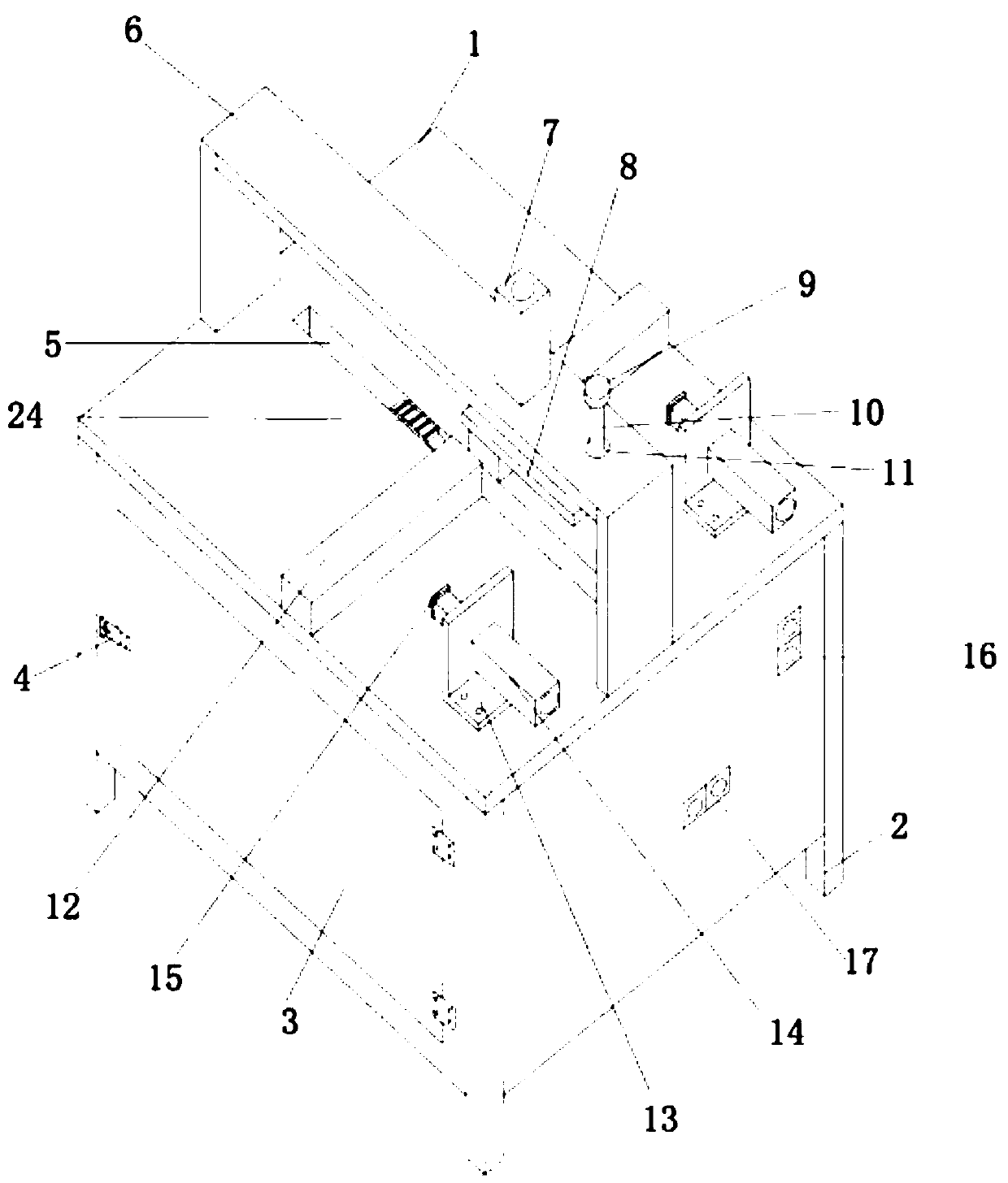
[0027] Such as figure 1 As shown, a safe and efficient slotting machine includes a workbench 1, and legs 2 are correspondingly provided at the bottom of the workbench 1. The workbench 1 is a hollow and airtight frame structure. The upper surface of the upper surface is correspondingly provided with a plurality of saw grooves 5 penetrating through the upper surface of the workbench 1, and a top beam 6 is correspondingly provided above the saw grooves 5;

[0028] The top of the top beam 6 is correspondingly provided with a top cylinder 7, the output shaft of the top cylinder 7 faces the saw groove 5, and the output shaft of the top cylinder 7 is connected with the plate-shaped top fastening block 8 correspondingly, so The top fastening block 8 is parallel to the saw groove 5, and a material fixing column 12 is correspondingly provided on the upper surface of the workbench 1, and the material fixing column 12 is perpendicular to the saw groove 5;

[0029] The upper surface of th...

Embodiment 2

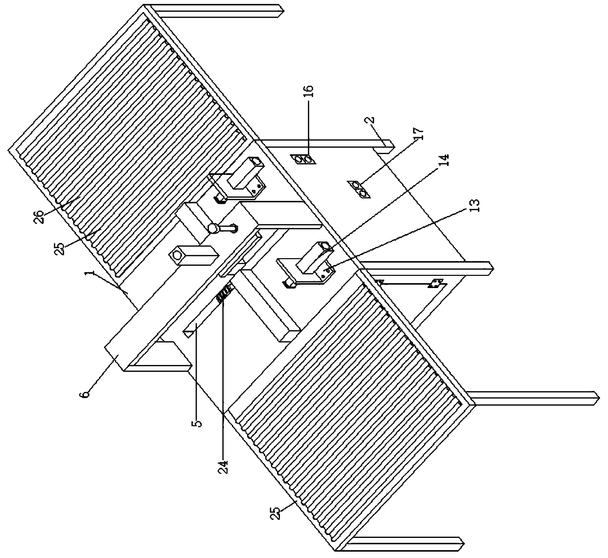
[0038] Such as figure 2 As shown, in this embodiment, the similarities with Embodiment 1 will not be repeated, and the difference is that a pair of outwardly protruding wingspans 25 are correspondingly provided on the upper surface of the workbench 1, so The upper surface of the wingspan 25 is flush with the upper surface of the workbench 1 , and the extending direction of the wingspan 25 is parallel to the material fixing column 12 . A plurality of rollers 26 are correspondingly arranged on the surface of the wingspan 25 , and the plurality of rollers 26 are parallel to the telescopic direction of the output shaft of the horizontal cylinder 14 . The setting of the cylinder 26 is conducive to the movement of the wood and improves work efficiency. When the length of the material to be grooved is long, the material to be grooved can be stably placed on it by setting the wingspan 25, avoiding the safety risk caused by the material to be grooved protruding too much from the work...


PUM


Abstract

The invention discloses a safe and efficient grooving machine. The safe and efficient grooving machine comprises a workbench. Supporting legs are correspondingly arranged at the bottom of the workbench. The workbench is of a hollow closed frame structure. A plurality of saw grooves penetrating the upper surface of the workbench are correspondingly formed in the upper surface of the workbench. Topbeams are correspondingly arranged above the saw grooves. Top air cylinders are correspondingly arranged on the tops of the top beams. Output shafts of the top air cylinders face the saw grooves. A plurality of horizontal air cylinder fixing bases are correspondingly arranged on the upper surface of the workbench. Output shafts of the horizontal air cylinders are opposite to material fixing columns. A motor moving air cylinder motor is correspondingly arranged in the workbench and correspondingly drives a grooving saw blade. The upper end of the grooving saw blade is correspondingly inserted in the saw grooves. The motor can move front and back, the grooving saw blade can be adjusted in an up-down lifting manner according to the needed grooving depth, the grooving saw blade can be replacedaccording to the grooving width, and one-time grooving forming can be conveniently and rapidly conducted.

Description

technical field [0001] The invention relates to the field of slotting equipment in the woodworking industry, in particular to a safe and efficient slotting machine. Background technique [0002] In the daily work of woodworking, it is often necessary to perform slotting operations on boards or wood. The existing slotting is usually done manually. The mechanical slotting equipment that gradually appears has low safety, complicated slotting operations, Low efficiency, unstable slotting quality and other shortcomings, therefore, it is necessary to design a safe and efficient slotting machine. Contents of the invention [0003] In order to overcome the defects in the prior art, a safe and efficient slotting machine is provided. [0004] The present invention realizes by following scheme: [0005] A safe and efficient slotting machine, comprising a workbench, correspondingly provided with outriggers at the bottom of the workbench, the workbench is a hollow and airtight frame ...

Claims


Application Information

Patent Timeline
Patent Type & Authority Applications(China)
IPC IPC(8): B27B5/29B27B5/24
CPCB27B5/24B27B5/29
Inventor 陈福建
Owner 厦门致尊科技有限公司
Why Eureka
Try Eureka