Folding wing structure of unmanned aerial vehicle

A technology for folding wings and unmanned aerial vehicles, applied in the field of unmanned aerial vehicles, can solve the problems of complex structural design, many parts, large size, etc., and achieve the effect of reducing processing costs and simplifying the folding mechanism

Pending Publication Date: 2020-07-31
西安深瞳智控技术有限公司
View PDF0 Cites 4 Cited by
  • Summary
  • Abstract
  • Description
  • Claims
  • Application Information

AI Technical Summary

Problems solved by technology

[0004] The purpose of the present invention is to provide a folding wing structure for unmanned aerial vehicles to overcome the fact that the existing cannon-launched unmanned aerial vehicles have many wing folding mechanism parts, complex structural design, relatively large size, and are not suitable for small cannon-launched unmanned aerial vehicles. Too applicable and high cost. The invention has few parts and simple processing, which simplifies the folding mechanism and reduces the processing cost of the drone. It is not sensitive to the structural size and can adapt to more miniaturized tube-shooting drones.

Method used


Image

  • Folding wing structure of unmanned aerial vehicle
  • Folding wing structure of unmanned aerial vehicle
  • Folding wing structure of unmanned aerial vehicle

Examples


Embodiment

[0030] The present invention is manually folded and unfolded automatically, ensuring that each movable surface is clean and smooth during assembly and use, and can be coated with grease if necessary.

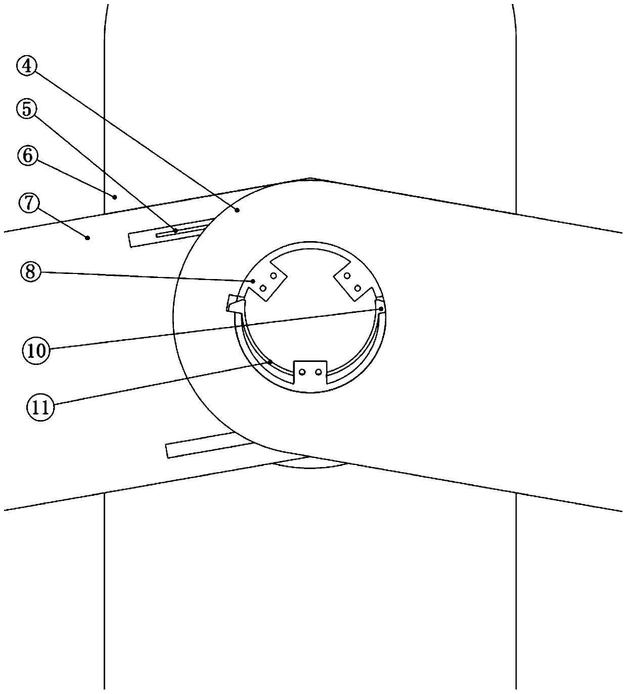
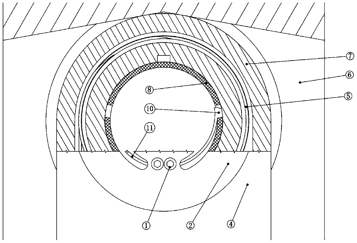
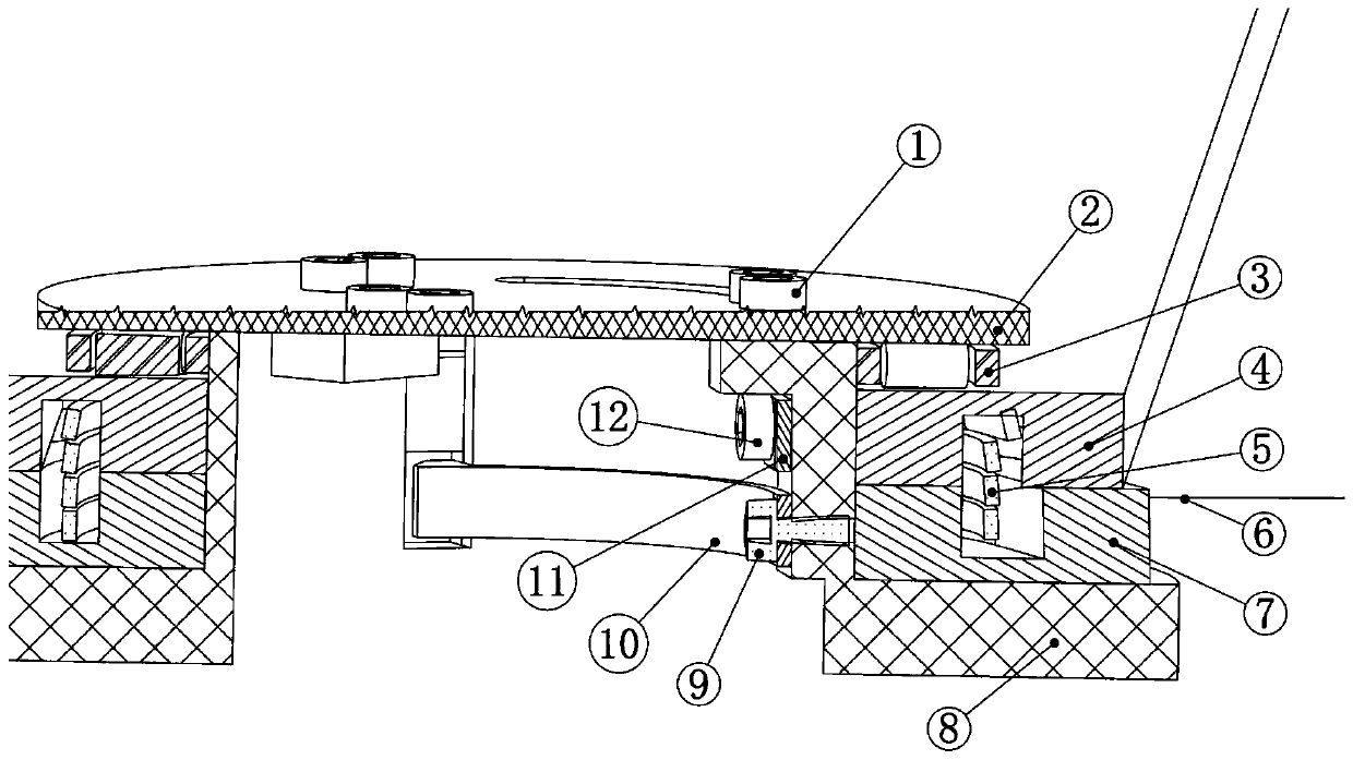
[0031] The rotating shaft 8 is embedded on the fuselage 6 by means of gluing or screwing. The rest of the components are mainly sleeved on the rotating shaft 8 by stacking one by one from bottom to top. The lower wing shrapnel 10 is installed in the inner cavity of the rotating shaft 8 with the first installation screw 9 . Install the upper wing shrapnel 11 in the inner cavity in the same way, and ensure that the locking block of the shrapnel is facing the notch position of the rotating shaft 8 . After making the locking groove of the lower wing 7 exactly opposite to the notch of the rotating shaft 8, put the lower wing 7 on the rotating shaft 8, and at this time, the torsion spring groove of the lower wing 7 is facing upward. Fully press the torsion spring 5 into the torsion ...


PUM


Abstract

The invention discloses a folding wing structure of an unmanned aerial vehicle, which comprises a rotating shaft embedded in a vehicle body, wherein a lower wing elastic sheet and an upper wing elastic sheet are mounted in an inner cavity of the rotating shaft from bottom to top, a first locking block and a second locking block are respectively arranged at the free ends of the lower wing elastic sheet and the upper wing elastic sheet, the first locking block and the second locking block are respectively matched with a first notch and a second notch which are formed in the rotating shaft, the outer side of the rotating shaft is sequentially sleeved with a lower wing and an upper wing from bottom to top, the upper surface of the lower wing and the lower surface of the upper wing are each provided with a groove, the two grooves are oppositely formed to form a torsional spring groove, a torsional spring is arranged in the torsional spring groove, and the upper inner sides of the lower wingand the upper wing are provided with a first locking groove and a second locking groove correspondingly; and the outer side of the rotating shaft is further sleeved with a roller bearing, a baffle isinstalled at the top of the rotating shaft, and the roller bearing is located between the upper wing and the baffle. The processing cost of the unmanned aerial vehicle is reduced, the folding wing structure is insensitive to the structural size, and the folding wing structure can adapt to a more miniaturized barrel-shooting unmanned aerial vehicle.

Description

technical field [0001] The invention belongs to the technical field of unmanned aerial vehicles, and in particular relates to a folding wing structure of an unmanned aerial vehicle. Background technique [0002] Tube-launched UAVs, as a special kind of UAVs, are used more and more frequently in information warfare, and they are highly valued for their high cost performance, multi-purpose capabilities, strong concealment and special operations capabilities. The small tube-firing drone is a kind of drone that can be stored in the launch tube. The wings are radially folded and stored in the tube. When in use, the drone is out of the tube, the wings are quickly unfolded, and it flies to the target area to perform reconnaissance and surveillance. , damage assessment and target attack tasks. The folding and unfolding of the wing is realized by the wing folding mechanism, and the folding mechanism is mainly composed of a rotating shaft, a power source for the unfolding of the wing...

Claims


Application Information

Patent Timeline
IPC IPC(8): B64C3/56
CPCB64C3/56B64U70/70
Inventor 刘勇
Owner 西安深瞳智控技术有限公司
Why Eureka
Try Eureka