
Separating device

A separation device, cylindrical technology, applied in blasting, mining equipment, earth-moving drilling, etc., can solve the problems of difficult operation, long construction period, scattered rock force, etc., and achieve the effect of convenient transportation and feeding

Inactive Publication Date: 2020-07-31
安徽企路石工程技术开发有限公司
View PDF0 Cites 0 Cited by
  • Summary
  • Abstract
  • Description
  • Claims
  • Application Information

AI Technical Summary

Problems solved by technology

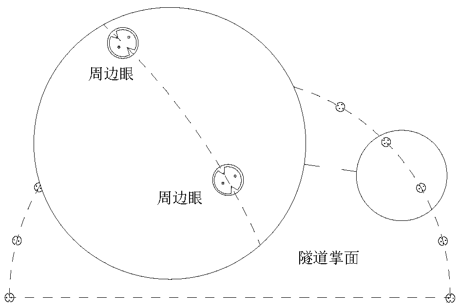
[0002] Palm blasting refers to blasting the end face of the tunnel to gradually advance the tunnel depth when excavating the tunnel. It is determined by the blasting quality of the peripheral eye. In the prior art, ordinary emulsion explosives are generally used for blasting. The force on the rock is relatively scattered during blasting, and defects such as concave or convex are often produced on the contour of the vault, which requires manual post-mortem. , high labor intensity and long construction period; therefore, technicians have developed a new type of blasting device, which is filled with emulsion explosives in a cylindrical shell, and the cylindrical shell is provided with a concave V-shaped energy-gathering groove. The principle of this device is similar to that of the armor-piercing projectile. It uses the V-shaped energy-gathering groove to accumulate the explosion energy, and can generate a large impact force in the direction of the opening of the V-shaped groove, thereby cutting the rock formation, such as figure 1 As shown, when the blasting device is used for palm blasting, it is mainly used for peripheral eye blasting. When filling the charge, it is necessary to align the V-shaped energy-gathering groove with the two adjacent peripheral eyes on both sides to achieve accurate arch contours. to cut
However, compared with ordinary emulsion explosives, this new type of blasting device needs to adjust the angle of each explosive when filling the explosives. In addition, after the explosives are loaded in place, it must be ensured that they do not deflect in the blasthole. The operation is difficult and the construction period long, affecting construction progress

Method used


Image

  • Separating device
  • Separating device
  • Separating device

Examples


Embodiment 1

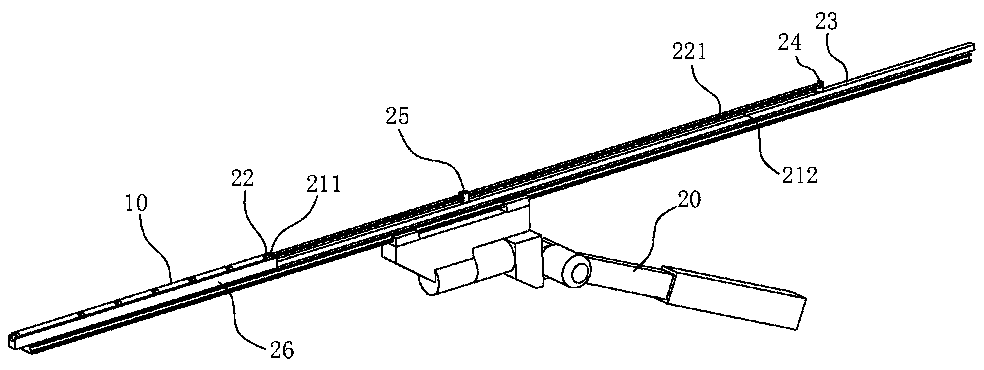
[0036] Such as figure 2 , 3 , 6, a palm blasting explosives layout system, the explosives include at least two cylindrical shells 10 coaxially arranged, such as Figure 9 , 10 , 11, two V-shaped energy-gathering grooves 11 sunk toward the center of the cylindrical shell 10 are symmetrically arranged on the peripheral surface of the cylindrical shell 10, and the length direction of the V-shaped energy-gathering grooves 11 is in line with the cylinder The axial direction of the cylindrical shell 10 is parallel; the emulsion explosive is filled in the cylindrical shell 10; as Figure 12 , 13, 14, the two ends of the cylindrical housing 10 are respectively provided with a first end seat 12 and a second end seat 13, and the first end seat 12 and the second end seat 13 are provided with a V-shaped poly A V-shaped groove connected to the energy groove 11, a positioning device is provided on the first end seat 12; the positioning device includes a positioning block 121 that is te...

Embodiment 2

[0047] A method for filling explosives by palm surface blasting using the system described in Embodiment 1, comprising the steps of:

[0048] Step 1: Butt the multi-stage explosives into a whole, and insert the V-shaped energy-gathering groove 11 on the two guide rods 21;

[0049] Step 2: Use the rotary drive unit to adjust the direction of the V-shaped energy-gathering groove 11 of the explosive, so that the two V-shaped energy-gathering grooves 11 are respectively facing two adjacent blastholes on both sides of the blasthole to be loaded;

[0050] Step 3: Use the drive mechanism to push the explosives as a whole to the inner end of the blast hole;

[0051] Step 4: The driving mechanism drives the guide rod 21 to be continuously pulled out of the blasthole, and at the same time drives the block seat 22 to be pulled out of the blast hole intermittently. The V-shaped energy-gathering groove 11 is pulled away, and then the explosive positioning device at the innermost end is ej...


PUM


Abstract

The invention belongs to the technical field of tunnel construction, and particularly relates to a separating device. The separating device comprises cylindrical shells with at least two ends coaxially arranged, wherein two V-shaped energy gathering grooves sunken towards the centers of the cylindrical shells are symmetrically formed in the circumferential faces of the cylindrical shells, every two adjacent cylindrical shells are in insertion fit through plug pins and insertion holes, and a locking mechanism is arranged in each cylindrical shell where the corresponding insertion hole is located. A plurality of single explosive bodies are detachably assembled together, explosive transferring and feeding are facilitated, the separating devices are arranged between the explosive single bodies, after an explosive assembly enters a shot hole, the single explosive bodies are separated in sequence, and uniform distribution of explosive is achieved. When all the single bodies are assembled, ashot line with a certain length needs to be reserved between the single bodies, and the length of the reserved shot line should be consistent with the distance between every two adjacent single bodiesafter explosive is arranged in the shot hole.

Description

technical field [0001] The invention belongs to the technical field of tunnel construction, and in particular relates to a separation device. Background technique [0002] Palm blasting refers to blasting the end face of the tunnel to gradually advance the tunnel depth when excavating the tunnel. It is determined by the blasting quality of the peripheral eye. In the prior art, ordinary emulsion explosives are generally used for blasting. The force on the rock is relatively scattered during blasting, and defects such as concave or convex are often produced on the contour of the vault, which requires manual post-mortem. , high labor intensity and long construction period; therefore, technicians have developed a new type of blasting device, which is filled with emulsion explosives in a cylindrical shell, and the cylindrical shell is provided with a concave V-shaped energy-gathering groove. The principle of this device is similar to that of the armor-piercing projectile. It use...

Claims


Application Information

Patent Timeline
Patent Type & Authority Applications(China)
IPC IPC(8): F42D1/08F42D3/04E21D9/00
CPCE21D9/006F42D1/08F42D3/04
Inventor 储顺清王辉
Owner 安徽企路石工程技术开发有限公司
Learn More