
Optical sensor internal orientation element calibration method based on linear array push-broom

An internal orientation element, optical sensor technology, applied in the aerospace field, can solve the problems of data waste, high-precision control data dependence, neglect and so on

Inactive Publication Date: 2020-07-31
WUHAN UNIV
View PDF1 Cites 7 Cited by
  • Summary
  • Abstract
  • Description
  • Claims
  • Application Information

AI Technical Summary

Problems solved by technology

However, the geometric calibration of active satellites in orbit still does not take into account the characteristics of the domestic linear array push-broom optical satellite imaging platform, resulting in a heavy dependence on high-precision control data during the geometric calibration process, especially the calibration of the inner azimuth elements, which leads to a large number of waste of data

Method used


Image

  • Optical sensor internal orientation element calibration method based on linear array push-broom
  • Optical sensor internal orientation element calibration method based on linear array push-broom
  • Optical sensor internal orientation element calibration method based on linear array push-broom

Examples


Embodiment Construction

[0094] In order to make the above objects, features and advantages of the present invention more comprehensible, the present invention will be further described in detail below in conjunction with the accompanying drawings and specific embodiments. The embodiments of the present invention are described in detail below. This embodiment is implemented on the premise of the technical solution of the present invention, and detailed implementation methods and specific operating procedures are provided, but the protection scope of the present invention is not limited to the following implementation example.

[0095] The data collected in the experiment of this embodiment are as follows: In order to verify the correctness of the geometric cross-checking method, 1:2000 digital orthophotos and digital elevation models covering the Songshan area and Tianjin area in Henan, my country were collected as checking control data. Among them, the coverage area of ​​Tianjin area is about 100km (...


PUM


Abstract

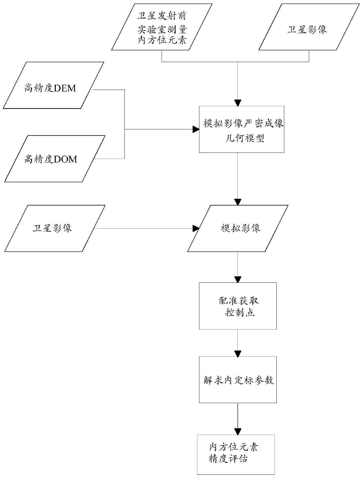
The invention provides an optical sensor internal orientation element calibration method based on linear array push-broom. The method comprises the following steps: constructing a rigorous geometric imaging model based on azimuth elements, an attitude orbit and a high-precision digital elevation model in a satellite-borne push-broom optical sensor, and generating an analog image; as for the satellite image and the analog image, using a high-precision registration algorithm combining phase correlation and least squares to obtain registration control points; and solving the external calibrationparameters by utilizing the registration control points in combination with a strict geometric imaging model, and further obtaining the internal calibration parameters. The method is based on the imaging mode of the linear array push-broom sensor, high-precision registration control points are adopted to achieve combined calibration of the satellite, the influence of system errors on the geometriccalibration precision of the satellite is avoided, the positioning precision of the satellite is improved, and the method has very important significance in guaranteeing the application effect of thesatellite in the field of dynamic observation.

Description

technical field [0001] The invention relates to the field of aerospace, in particular to a method for calibrating azimuth elements in an optical sensor based on linear array push-broom. Background technique [0002] After more than 30 years of development, my country's aerospace technology has made great progress, and has formed a remote sensing satellite system for earth observation consisting of resources, meteorology, ocean, and environment. Especially under the impetus of the "High Resolution Earth Observation System" national major science and technology project, through innovations in the development of platform sensors, multi-satellite networking, and ground data processing, the spatial resolution and time resolution of my country's remote sensing satellites The rate and data quality have been greatly improved, providing information services and decision support for my country's modern agriculture, disaster prevention and mitigation, resources and environment, public s...

Claims


Application Information

Patent Timeline
Patent Type & Authority Applications(China)
IPC IPC(8): G01C25/00
CPCG01C25/00
Inventor 张过蒋永华昌明明
Owner WUHAN UNIV
Learn More