Dry-type fluorescence immunoassay detector
A fluorescent immunodetector technology, which is applied in the field of dry fluorescent immunodetector, can solve the problems of cumbersome manual steps, and achieve the effects of improving the efficiency of card retrieval, convenient storage and use, and simple structure
- Summary
- Abstract
- Description
- Claims
- Application Information
AI Technical Summary
Benefits of technology
Problems solved by technology
Method used
Image
Examples
Embodiment 1
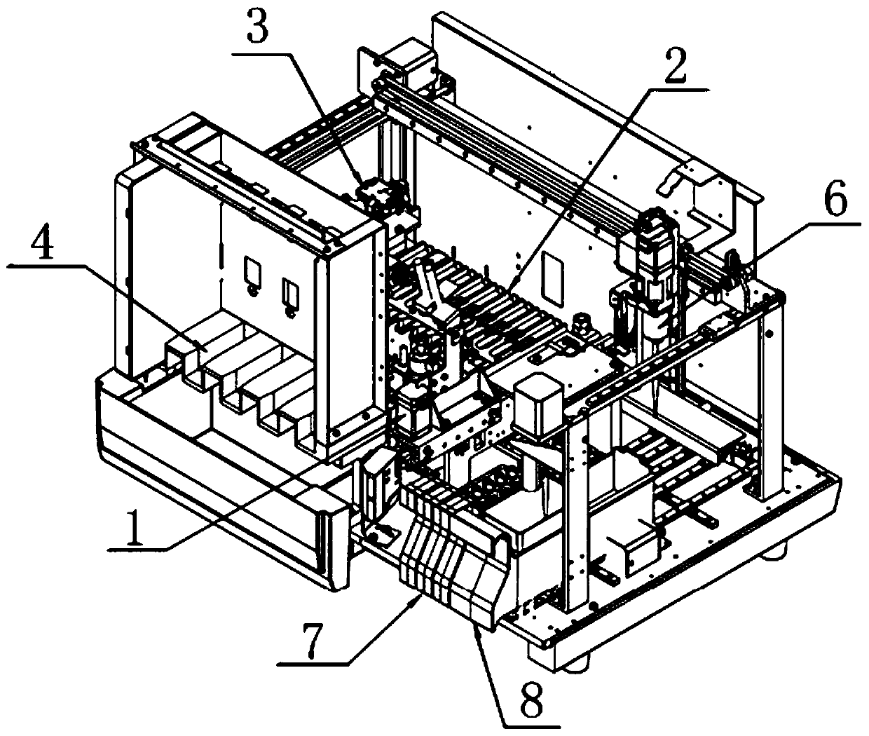
[0056] like Figure 1-13 As shown, a dry fluorescent immunoassay instrument includes a transportation mechanism 1, an incubation mechanism 2, a lighting mechanism 3, a reagent cartridge storage mechanism 4, a sample loading mechanism 6, a sample rack mechanism 7, and a suction head integrated on the chassis. Mechanism 8 and movable frame 10;
[0057] The transportation mechanism 1 is used for transporting the reagent card 5, the incubation mechanism 2 is used for pretreatment of the reagent card 5 and the sample solution, and the sample adding mechanism 6 is used for adding the sample solution to the reagent card 5, The suction head mechanism 8 is used to quantitatively absorb the sample liquid, the sample rack mechanism 7 is used to store the test tube 9, and the sample liquid is stored in the test tube 9, and the light-collecting mechanism 3 is used to treat the pretreated reagent card 5 Perform optical information data collection and output, and the movable frame 10 is use...
Embodiment 2
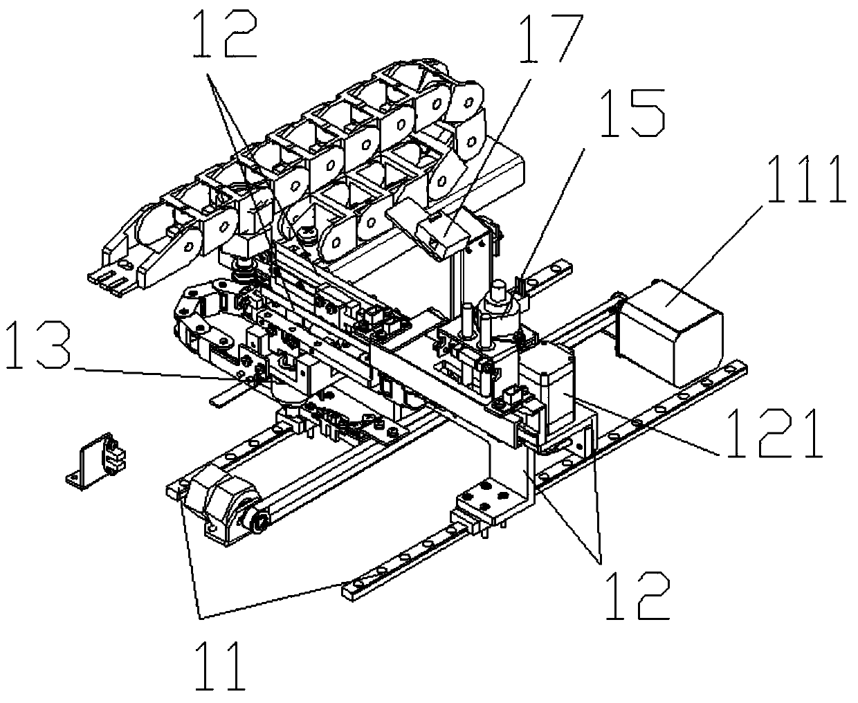
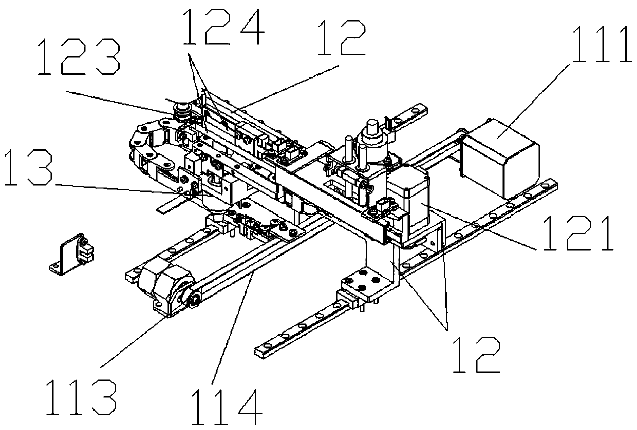
[0074] like Figure 1-13 As shown, this embodiment is based on Embodiment 1, and the bottom rail 11 is provided with a transmission device a for driving the side guide rail 12 to slide on the bottom rail 11. The driving motor a111, the idler assembly a113 arranged at the other end of the sliding direction of the bottom guide rail 11, the output shaft of the driving motor a111 is connected with the idler assembly a113 through the belt a114; The transmission device b in which the fork mechanism 13 slides on the side guide rail 12, the transmission device b includes a driving motor b121 arranged at one end of the side guide rail 12 in the sliding direction, and an idler wheel assembly b123 arranged at the other end of the side guide rail 12 in the sliding direction , the output shaft of the drive motor b121 is connected to the idler assembly b123 through the belt b124; the piercing mechanism 15 includes a reagent card bracket 151 for fixing the reagent card, and is arranged above...
PUM
 Abstract
Description
Claims
Application Information
 - R&D
- Intellectual Property
- Life Sciences
- Materials
- Tech Scout
- Unparalleled Data Quality
- Higher Quality Content
- 60% Fewer Hallucinations
Browse by: Latest US Patents, China's latest patents, Technical Efficacy Thesaurus, Application Domain, Technology Topic, Popular Technical Reports.
© 2025 PatSnap. All rights reserved.Legal|Privacy policy|Modern Slavery Act Transparency Statement|Sitemap|About US| Contact US: help@patsnap.com


