Distributed optical fiber temperature measurement power cable

A distributed optical fiber and power cable technology, which is applied to power cables, power cables including optical transmission elements, and power cables with shielding/conducting layers, etc. , increase the weight and cost of cables, etc., to achieve the effects of automatic measurement and online temperature monitoring, enhanced vibration reduction, and good low-frequency shielding.

Inactive Publication Date: 2020-07-31
JIANGSU DONGQIANG
View PDF0 Cites 1 Cited by
  • Summary
  • Abstract
  • Description
  • Claims
  • Application Information

AI Technical Summary

Problems solved by technology

However, when the temperature measuring optical fiber is placed in the power cable for temperature measurement, due to the stretching, extrusion and bending of the power cable during laying or use, it may not only cause various mechanical damage to the optical fiber, but also damage the optical fiber. The working posture of the optical fiber causes the temperature measuring fiber to generate polarized light, resulting in a large temperature measurement error. For this reason, the existing optical fibers used for online temperature measurement of power cables often have a relatively complicated sheath layer, and this sheath layer It will block or delay the heat transfer of the cable or form uneven conduction, which will cause large errors in optical fiber measurement
At the same time, most of the existing shielding structures use metal shielding structures, which not only need to consume more precious metals, increase the weight and cost of the cable, but also affect the heat conduction of the cable and the accurate measurement of temperature

Method used


Image

  • Distributed optical fiber temperature measurement power cable
  • Distributed optical fiber temperature measurement power cable
  • Distributed optical fiber temperature measurement power cable

Examples


Embodiment 1

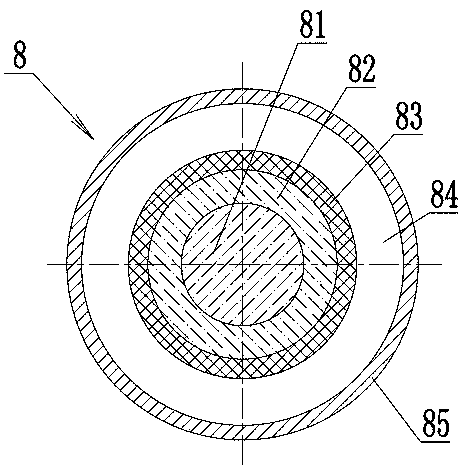
[0024] Example 1: The weight percentage components of the thermal conductive filling paste 84 are: 72% thermal oil, 20% gelling agent, 4% oil separation inhibitor, 1.5% antioxidant, 0.0018% defoamer, and the rest is water absorbent. The heat transfer oil mentioned above is synthetic heat transfer oil, the gelling agent is fumed silica, the antioxidant is alkylphenol antioxidant, the oil separation inhibitor is ethylene propylene rubber or ethylene propylene rubber, the water absorbent is silica gel, and the defoamer is emulsified silicone oil.

Embodiment 2

[0025] Example 2: The weight percentage components of the thermally conductive filling paste 84 are: 72.5% of thermal oil, 18% of gelling agent, 5% of oil separation inhibitor, 2% of antioxidant, 0.002% of defoamer, and the rest are water absorbing agents. The heat-conducting oil is synthetic heat-conducting oil, the gelling agent is fumed silica, the antioxidant is alkylphenol antioxidant, the oil separation inhibitor is diblock polymer, the water-absorbing agent is silica gel, and the defoaming agent is emulsified silicone oil.

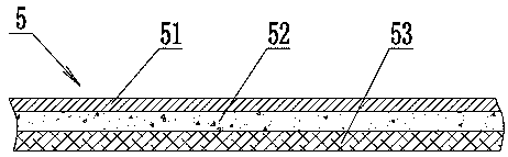
[0026] Such as image 3 As shown, the thermally conductive shielding tape wrapped into the shielding layer 5 adopts a multi-layer composite structure, and its substrate layer adopts a graphite base layer 52, and the graphite base layer 52 adopts a synthetic graphite film with a thickness of 45 μm or a natural stone with a thickness of 100 μm. Ink film, or a mixed film of synthetic graphite and natural graphite. One side of the graphite base layer 52 i...


PUM

PropertyMeasurementUnit
diameteraaaaaaaaaa

Abstract

The invention discloses a distributed optical fiber temperature measurement power cable, which comprises a metal wire armor layer. At least one temperature measurement optical fiber is inserted into armor steel wires arranged in sequence; the temperature measurement optical fiber comprises a temperature measurement fiber core and an optical fiber wrapping layer wrapping the outer side of the temperature measurement fiber core, a heat conduction layer wraps the optical fiber wrapping layer, the periphery of the heat conduction layer is sleeved with metal outer pipes at intervals, and the spacebetween the heat conduction layer and the metal outer pipes is filled with heat conduction filling paste. The heat-conducting filling paste comprises the following components in percentage by weight:18%-20% of a gelatinizing agent, 3%-5% of an oil separation inhibitor, 1%-2% of an antioxidant, 2%-2.5% of a water absorbent, 0.0015%-0.002% of a defoaming agent and the balance of a heat-conducting oil, wherein the shielding layer is formed by wrapping a heat conduction shielding belt, the heat conduction shielding belt comprises a graphite diaphragm, one side surface of the graphite diaphragm isplated with a metal plating layer, and the other side surface of the graphite diaphragm is provided with a heat conduction adhesive layer. The power cable can accurately monitor the operation condition of the cable in real time.

Description

Technical field [0001] The present invention relates to the technical field of power cables, in particular to a power cable including a conductive cable core and a temperature measuring optical fiber. The power cable can not only transmit electric energy, but also monitor the operating temperature of the cable in a timely manner. Background technique [0002] Power cables are widely used in urban underground power grids, railway power grids, internal power supply of industrial and mining enterprises, and underwater power transmission lines. With the continuous expansion of power cable applications, the laying environment of power cables has become more complex, and power cables have changed from simple Electric power transmission is developing in the direction of multi-purpose and multi-purpose such as corrosion resistance, flame retardant, water and moisture resistance. [0003] With the vigorous development of high-speed rail construction, the number of applications of power cabl...

Claims


Application Information

Patent Timeline
Patent Type & Authority Applications(China)
IPC IPC(8): H01B7/32H01B7/42H01B7/22H01B9/00H01B9/02G01K1/14G01K11/32
CPCH01B7/324H01B7/428H01B9/005H01B9/02H01B7/22G01K1/14G01K11/32
Inventor 王子纯吴荣美王立忠于浜邵秀琴王明媚
Owner JIANGSU DONGQIANG
Why Eureka
Try Eureka