Optical fiber temperature measurement power cable with uniform temperature electric field

An optical fiber temperature measurement and uniform temperature technology, which is applied to power cables with shielding/conductive layers, power cables, and power cables including optical transmission components, etc. Light, delaying the transmission of cable heat, etc., to achieve the effect of automatic measurement and online temperature monitoring, uniform electric field distribution, and improved withstand voltage level

Active Publication Date: 2021-10-19
JIANGSU DONGQIANG
View PDF6 Cites 0 Cited by
  • Summary
  • Abstract
  • Description
  • Claims
  • Application Information

AI Technical Summary

Problems solved by technology

However, when the temperature measuring optical fiber is placed in the power cable for temperature measurement, due to the stretching, extrusion and bending of the power cable during laying or use, it may not only cause various mechanical damage to the optical fiber, but also damage the optical fiber. The working posture of the optical fiber causes the temperature measuring fiber to generate polarized light, resulting in a large temperature measurement error. For this reason, the existing optical fibers used for online temperature measurement of power cables often have a relatively complicated sheath layer, and this sheath layer It will block or delay the heat transfer of the cable or form uneven conduction, which will cause large errors in optical fiber measurement
At the same time, most of the existing shielding structures use metal shielding structures, which not only need to consume more precious metals, increase the weight and cost of the cable, but also affect the heat conduction of the cable and the accurate measurement of temperature

Method used


Image

  • Optical fiber temperature measurement power cable with uniform temperature electric field
  • Optical fiber temperature measurement power cable with uniform temperature electric field
  • Optical fiber temperature measurement power cable with uniform temperature electric field

Examples


Embodiment 1

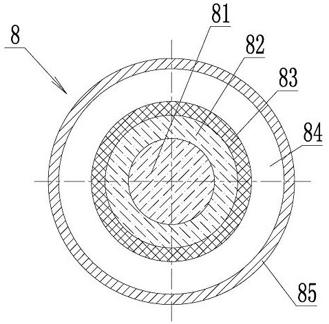
[0028] Embodiment 1: The components by weight of the heat conduction filling paste 84 are: heat conduction oil 72%, gelling agent 20%, oil separation inhibitor 4%, antioxidant 1.5%, defoamer 0.0018%, and the rest is water absorbing agent. The above-mentioned heat transfer oil is synthetic heat transfer oil, the gelling agent is fumed silica, the antioxidant is alkylphenol antioxidant, the oil separation inhibitor is ethylene propylene rubber or rubber, the water absorbing agent is silica gel, and the defoaming agent is emulsified silicone oil.

Embodiment 2

[0029] Embodiment 2: The components by weight of the thermally conductive filling paste 84 are: 72.5% of thermally conductive oil, 18% of gelling agent, 5% of oil separation inhibitor, 2% of antioxidant, 0.002% of defoamer, and the rest is water absorbing agent. The above-mentioned heat-conducting oil is synthetic heat-conducting oil, the gelling agent is fumed silica, the antioxidant is alkylphenol antioxidant, the oil separation inhibitor is a double-block polymer, the water-absorbing agent is silica gel, and the defoaming agent is emulsified silicone oil.

[0030] Such as Figure 4 As shown, the thermally conductive shielding tape wrapped into the shielding layer 5 adopts a multi-layer composite structure, and the base layer is made of graphite base layer 52, and the graphite base layer 52 is made of artificially synthesized graphite film with a thickness of 45 μm, or natural stone with a thickness of 100 μm. Ink film, or a mixed film of synthetic graphite and natural graph...


PUM


Abstract

The invention discloses an optical fiber temperature-measuring power cable with a uniform temperature and electric field. Conductive fillets are embedded in the corner arc gap of the conductor cable core tile-shaped conductor, and a conductive film is embedded in the arc surface gap between the center conductor and the tile-shaped conductor. At least one temperature-measuring optical fiber is inserted in the armored steel wires arranged in sequence; the temperature-measuring optical fiber includes a temperature-measuring fiber core, and an optical fiber cladding coated on the outside of the temperature-measuring fiber core, and a heat-conducting layer is coated on the optical fiber cladding , a metal outer tube is set at intervals on the outer periphery of the heat conduction layer, and a heat conduction filling paste is filled between the heat conduction layer and the metal outer tube; the components of the heat conduction fill paste are: gelling agent, oil separation inhibitor, antioxidant, water absorbing agent , defoamer and heat-conducting oil; the shielding layer is wrapped by a heat-conducting shielding tape, which includes a graphite diaphragm, one side of the graphite diaphragm is coated with a metal coating, and the other side of the graphite diaphragm There is a thermally conductive adhesive layer on it. The power cable can monitor the operation of the cable in real time, and has a uniform temperature field and electric field of the cable core.

Description

technical field [0001] The invention relates to the technical field of power cables, in particular to a power cable including a conductive cable core and a temperature-measuring optical fiber. The power cable can not only transmit electric energy, but also monitor the operating temperature of the cable in a timely manner. Background technique [0002] With the vigorous development of high-speed railway construction, the number of applications of power cables in railway power supply lines is also increasing day by day. The working status of power cables determines the quality and safety of power supply to a large extent. Preventing cable faults, reducing the failure rate during cable operation, and improving the reliability of cable power supply are particularly important for the safe and efficient operation of railways. [0003] Regardless of whether it is a power cable used in a railway power supply system or a power cable used in other power supply systems, the core of the...

Claims


Application Information

Patent Timeline
Patent Type & Authority Patents(China)
IPC IPC(8): H01B7/32H01B7/42H01B7/22H01B9/00H01B9/02G01K1/14G01K11/32
CPCH01B7/324H01B7/428H01B9/005H01B9/02H01B7/22G01K1/14G01K11/32
Inventor 王子纯吴荣美王立忠于浜唐秀芹王明媚
Owner JIANGSU DONGQIANG
Why Eureka
Try Eureka