Feeding and reclaiming manipulator

A reclaiming manipulator and free technology, applied in the field of manipulators, can solve the problems of inaccurate position, sticking and offset of circuit board punching, and achieve the effect of avoiding gaps

Inactive Publication Date: 2020-08-04
陈志后
View PDF0 Cites 3 Cited by
  • Summary
  • Abstract
  • Description
  • Claims
  • Application Information

AI Technical Summary

Problems solved by technology

[0003] Based on the inventor's discovery above, the existing feeding and retrieving manipulator mainly has the following deficiencies, such as: the manipulator is clamping the circuit board, and some debris will stick to the end surface of the clamp. When the circuit board is clamped, the circuit board and the jig are supported by debris, so that there is a gap between the circuit board and the jig, which causes the jig to clamp the circuit board and place it on the punching seat, and the circuit board is punched. inaccurate position

Method used


Image

  • Feeding and reclaiming manipulator
  • Feeding and reclaiming manipulator
  • Feeding and reclaiming manipulator

Examples


Embodiment 1

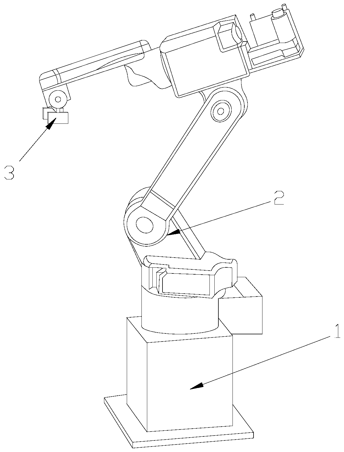
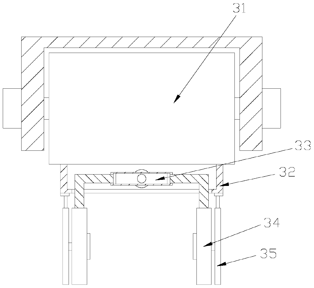
[0026] Example 1: Please refer to Figure 1-Figure 5 , the specific embodiment of the present invention is as follows: its structure comprises support base 1, free arm 2, clamp 3, and the upper end of described support base 1 is equipped with free arm 2, and described clamp 3 is installed on the upper end of free arm 2, described The fixture 3 includes a roller 31, a support block 32, a piston 33, a clamping block 34, and a push block 35. The bottom of the roller 31 is embedded with a support block 32, and the piston 33 is installed in the middle of the support block 32. There are two clamping blocks 34, which are respectively connected to the two ends of the piston 33; Cooperate.

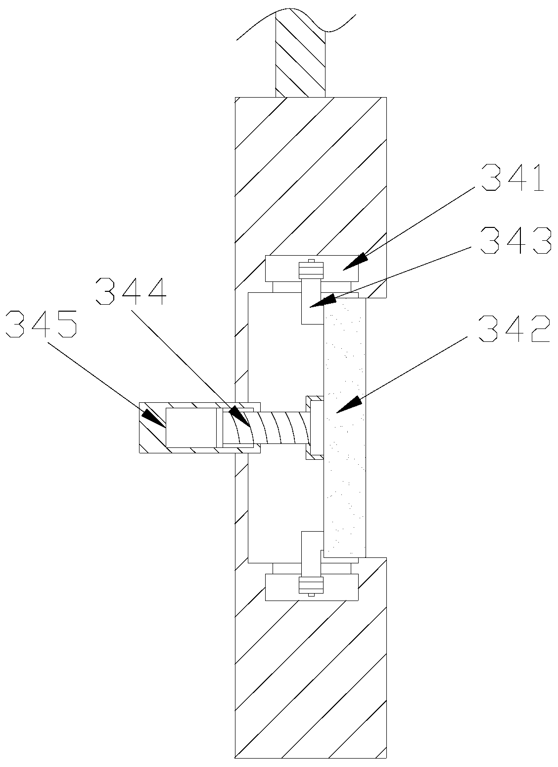
[0027] The clamping block 34 includes a rolling groove 341, a scraping block 342, a rolling shaft 343, a threaded rod 344, and a threaded card body 345. On the side, the scraping block 342 is located in the middle of the two rolling grooves 341, and the rolling shaft 343 is provided with two, whi...

Embodiment 2

[0031] Example 2: Please refer to Figure 6-Figure 8 The specific embodiment of the present invention is as follows: the scraper rod a34 includes a rod body b1, a connecting hole b2, and a rubber block b3, the front end of the rod body b1 is provided with a connecting hole b2, and the connecting hole b2 runs through the rod body b1. A rubber block b3 is attached to the bottom of the rod body b1 , and the rod body b1 is arc-shaped, which facilitates pushing the scraped debris to the end of the rod body b1 so that the debris falls from the clamping block 34 .

[0032] The rubber block b3 includes a rubber body b31, a groove b32, and a guide b33. The bottom end of the rubber body b31 is provided with a groove b32, and the guide b33 is installed at the end of the rubber body b31. The groove b32 It is stepped, so that debris moving towards the outer end of the rubber body b31 will be caught by the groove b32, and the debris will not move back.

[0033]The guiding device b33 includ...


PUM


Abstract

The invention discloses a feeding and reclaiming manipulator. The structure of the feeding and reclaiming manipulator comprises a support base, a free arm and a clamp; the free arm is installed at theupper end of the support base; the clamp is installed at the upper end of the free arm; the clamp comprises a roller, a support block, a piston, a clamping block and a push block; the clamping blockcomprises a rolling groove, scraping block, a rolling shaft, a threaded rod, and a threaded clamp body; the scraping block comprises a fixed base, a movable groove and a scraping body; and the scraping body comprises a fixed rod, a main rod, a rotating shaft, a scraping rod, and an elastic telescopic rod. According to the feeding and reclaiming manipulator provided by the invention, the threaded rod drives the scraping block to rotate, so that the inertia generated by the rotation of the scraping body can drive the scraping rod to turn outwards, so that the scraping rod can scrape off debris adhered to the clamping block, so that debris generated by punching is prevented from being attached to the end face of the clamp, a gap between a circuit board and the clamp is avoided, and a drillingmachine can accurately punch the circuit board.

Description

technical field [0001] The invention relates to the field of manipulators, in particular to a feeding and retrieving manipulator. Background technique [0002] A manipulator is an automatic operating device that can imitate certain movement functions of the human hand and arm to grab, carry objects or operate tools according to a fixed program. The feature is that various expected operations can be completed through programming. The structure and performance have both the advantages of man and robot. When the circuit board is used to install electronic components, it is necessary to punch holes on the side of the board. In order to To speed up the drilling speed, it is necessary to use the robot to clamp the circuit board and place it on the punching seat of the punching machine, so as to speed up the drilling speed of the circuit board. When the circuit board is punched, the friction between the drill bit and the board body will produce debris , the debris falls on the upp...

Claims


Application Information

Patent Timeline
Patent Type & Authority Applications(China)
IPC IPC(8): B25J11/00
CPCB25J11/005
Inventor 陈志后
Owner 陈志后
Why Eureka
Try Eureka